Models and manufacturing numbers in this manual. 2002 models are listed in bold. ACO1520AB ACO1520AC ACO1520AW Service Over The Range 2001 and 2002 Domestic Microwave Ovens This manual replaces RS2100011 Revision 0.
Important Information Pride and workmanship go into every product to provide our customers with quality products. It is possible, however, that during its lifetime a product may require service. Products should be serviced only by a qualified service technician who is familiar with the safety procedures required in the repair and who is equipped with the proper tools, parts, testing instruments and the appropriate service manual.
Table of Contents Disassembly Procedures Grille ........................................................................ 18 Door Assembly ........................................................ 18 Door Disassembly ................................................... 18 Control Panel .......................................................... 19 P.C. Board ............................................................... 19 Control Key Panel ................................................... 20 Outer Case ....
Important Product Information ! ! WARNING WARNING To avoid risk of electrical shock, injury or death, make sure these grounding instructions are followed. Precautions to be observed before and during servicing to avoid possible exposure to excessive microwave energy or electrical shock, disconnect power to oven. Grounding Instructions (A) Do not operate or allow oven to be operated with door open.
Important Safety Information ! 7. In the area of the transformer, capacitor, diode, and magnetron there is HIGH VOLTAGE. When the unit is operating - keep this area clean and free of anything which could possibly cause an arc or ground, etc. 8. Do not for any reason defeat the interlock switches, there is no valid reason for this action at any time; nor will it be condoned by Maytag. 9. IMPORTANT: Before returning a microwave to a customer, check for proper switch interlock action.
Microwave Leakage Testing ! Measurement With the Outer Panel Removed WARNING Check for radiation leakage after servicing. Should the leakage be more than 4mW/cm2 inform Maytag immediately. After repairing or replacing any radiation safety device, keep a written record for future reference, as required by DHHS and HEW regulations. This requirement must be strictly observed. In addition, the leakage reading must be recorded on the service repair ticket while in the customer’s home.
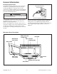
General Information Please read the owner’s manual information. It will tell how to use all the features of this microwave oven. Parts and Accessories Purchase replacement parts and accessories over the phone. To order accessories for your product call: Location of Model Number To request service information or replacement parts, the service center will require the complete model number of your microwave oven. The number is located on the oven front as shown in the illustration below.
General Information Grounding Instructions This appliance must be grounded. If an electrical short circuit occurs, grounding reduces the risk of electric shock by providing an escape wire for the electric current. The cord for this appliance has a grounding wire with a grounding plug. Put the plug into an outlet that is properly installed and grounded. ! Properly Polarized and Grounded Outlet WARNING To avoid risk of electric shock, personal injury or death, use grounding plug properly.
Testing Procedures ! WARNING Disconnect power before performing the following procedures unless testing requires it. NOTES: • Perform microwave energy leakage test if unit is serviced for any reason. • Verify wire leads are connected to correct positions. • When removing wire terminal plugs from connectors, grasp the connector, not the wires. Interlock Monitor Switch Test When the door is opened slowly, an audible click should be heard.
Testing Procedures ! WARNING Disconnect power before performing the following procedures unless testing requires it. 4. Measure resistance of the terminals on the high voltage transformer with meter on R x 1 scale. Reading should be indicated as follows: Primary winding ......less than 1.0 ohms Filament winding ....less than 1.0 ohms Secondary winding . approximately 50 to 120 ohms 5. Measure resistance of the terminals on the high voltage transformer with meter on high scale.
Testing Procedures ! WARNING Disconnect power before performing the following procedures unless testing requires it. 3. Disconnect ribbon connector by siding top part of connector upward. Once in released position remove ribbon from connector by siding ribbon side-to-side. ACO1560/MMV5156 models continued Easy Cook Time Defrost Start Sensor Potato Sensor Popcorn Program NOTE: Caution should be used when removing cable from connector. Ribbon cable has two holes which holds the lock ribbon in place.
Testing Procedures ! WARNING Disconnect power before performing the following procedures unless testing requires it. Circuit Board Oven Thermostat Following symptoms indicate a failed circuit board. 1. Disconnect power to oven and remove control panel, (see "Control Panel" section). 2. Discharge high voltage capacitor, (see "High Voltage Capacitor" section). 3. Remove outer case, (see "Outer Case" section). 4. Lift air duct securing thermostat to oven cavity. 5. Disconnect wires from oven thermostat.
Troubleshooting Procedures "PLEASE TOUCH TIME OF DAY" does not appear in the display, when unit is plugged in. 1. Check power supply. 2. Check fuse. 3. Check oven thermostat. Measure voltage between pin 1 and pin 3 of CN1 connector YES Is 120 volts indicated. Replace circuit board. NO Verify proper connection of circuit board. Display does not indicate correct number pressed or correct indication when programmed. Is continuity indicated when key pad is pressed. Unit operates.
Troubleshooting Procedures Check: 1. Touch Keypad. Measure resistance of CN2 between pin 1 and pin 3 with door closed. Display does not count down when START is pressed. Is continuity indicated. Verify proper connection of ribbon connector. YES NO NO Adjust or replace door sensing switch. Reconnect ribbon connector for proper connection. Does ribbon connector have proper connection. YES Replace circuit board. Unit operates.
Troubleshooting Procedures Check: 1. Air Vents. Unit operates normal, but little or no heating is produced with an oven load. Does fan motor operate when START is pressed. Check if fan motor operates when START is pressed. YES Measure resistance of high voltage capacitor. NO NO Place a jumper wire across thermostat. Does fan motor operate. Replace high voltage capacitor. Does capacitor have correct resistance. See to Testing Procedures on page 10. YES Replace magnetron. YES Replace thermostat.
Troubleshooting Procedures Check: 1. Primary and Secondary Interlock Switches. 2. Thermostat. Unit does not heat even if display counts down when START pad is pressed for high power. Does relay contacts measure correct resistance. Check the contacts of RY2 relay. YES Verify proper connection of ribbon connector. NO Replace circuit board. Does ribbon connector have proper connection. NO YES Reconnect ribbon connector for proper connection. Replace circuit board. Unit operates.
Troubleshooting Procedures Check: 1. Power Supply. 2. Fuse. Ventilation fan does not operate when FAN HIGH/LOW pad is pressed. Does magnetron thermal fuse and oven thermostat have the correct resistance. Measure resistance of magnetron thermal fuse and oven thermostat. YES Verify proper connection of ribbon connector. YES NO NO Test and replace failed component. Does ribbon connector have proper connection. Replace circuit board. Reconnect ribbon connector for proper connection.
Disassembly Procedures ! To avoid the risk of electrical shock, personal injury or death; disconnect power to oven and discharge capacitors before following any disassembly procedure. WARNING NOTE: All procedures are written for the ACO18*, JMV8196*, MMV4184, and MMV5186* models. Specific instruction for the ACO15*, MMV5156* models are as described in the procedures. Door Removal 1. Disconnect power to oven and remove grille, (see "Grille" procedure). 2.
Disassembly Procedures ! To avoid the risk of electrical shock, personal injury or death; disconnect power to oven and discharge capacitors before following any disassembly procedure. WARNING 6. Remove door handle by placing a hand on door panel next to the top of the door handle. Twist door panel towards the inside of door and pulling on the top portion of the door handle in a quick jerking motion. Control Panel The control panel is made up of several components, such as p.c. board and touch panel.
Disassembly Procedures ! CN1 CN2 CN5 FPC (S1) Relay 2 To avoid the risk of electrical shock, personal injury or death; disconnect power to oven and discharge capacitors before following any disassembly procedure. WARNING Control Key Panel Main power connector Primary switch Humidity sensor (some models) Ribbon connector for key panel Relay connector Screw The key panel has one ribbon connection on the p.c. board. The key panel pads can be checked through a continuity test.
Disassembly Procedures ! To avoid the risk of electrical shock, personal injury or death; disconnect power to oven and discharge capacitors before following any disassembly procedure. WARNING 9. Reassemble in reverse order. Interlock Door Latch Switches Primary switch is operated by bottom latch pawl. Interlock Switch Removal 1. Disconnect power to oven and remove control panel, (see "Control Panel" procedure). 2. Discharge high voltage capacitor, (see "High Voltage Capacitor" procedure). 3.
Disassembly Procedures ! To avoid the risk of electrical shock, personal injury or death; disconnect power to oven and discharge capacitors before following any disassembly procedure. WARNING 5. Hold latch board securely for proper switch operation and door fit, retighten screws. 6. Open the oven door slowly, watching the switches. Verify switches release in the following order.
Disassembly Procedures ! To avoid the risk of electrical shock, personal injury or death; disconnect power to oven and discharge capacitors before following any disassembly procedure. WARNING Transformer Magnetron High voltage transformer can be serviced through the front of the unit. Magnetron is mounted on the side of the cavity to provide a top feed single waveguide. Power Transformer Removal 1. Disconnect power to oven and remove control panel, (see "Control Panel" procedure). 1.
Disassembly Procedures ! To avoid the risk of electrical shock, personal injury or death; disconnect power to oven and discharge capacitors before following any disassembly procedure. WARNING Magnetron Thermal Fuse Oven Thermostat NOTE: Thermal fuse is not resettable. The oven thermostat is on the air duct assembly. Thermostat is a resettable thermostat. 1. Disconnect power to oven and remove control panel, (see "Control Panel" procedure). 2.
Disassembly Procedures ! To avoid the risk of electrical shock, personal injury or death; disconnect power to oven and discharge capacitors before following any disassembly procedure. WARNING 3. Open the oven door, remove turntable, and gently pry upward on turntable shaft. 4. Disconnect wire leads from turntable motor. Base Thermostat The base thermostat is located behind the control panel assembly. NOTE: Thermostat is a resettable thermostat. 1.
Wiring Diagram and Schematic ! To avoid the risk of electrical shock, personal injury or death; disconnect power to oven and discharge capacitors before following any disassembly procedure. WARNING ACO1520* and ACO1530* Models 16021668 Rev.
Wiring Diagram and Schematic ! To avoid the risk of electrical shock, personal injury or death; disconnect power to oven and discharge capacitors before following any disassembly procedure. WARNING ACO1560* and MMV5156* Models ©2002 Maytag Appliances Company 27 16021668 Rev.
Wiring Diagram and Schematic ! To avoid the risk of electrical shock, personal injury or death; disconnect power to oven and discharge capacitors before following any disassembly procedure. WARNING ACO18*, JMV8196*, MMV4184, and MMV5186* Models 16021668 Rev.
Installation Instruction Appendix A ©2002 Maytag Appliances Company A–1 16021668 Rev.
Installation Instruction Proper installation is the installer’s responsibility! Write the model & serial numbers on the owner’s manual. The model number label is located on the oven front. Model Number Label Electrical rating of this oven: 120V AC 60Hz. • 13 A / 1500 W (Microwave oven, Cooktop Lamps, Ventilation Fan) • You need a DEDICATED 120VAC / 60Hz / 20A, fused electrical supply (located in the cabinet above the microwave as close as possible to the microwave) serving only the microwave.
Installation Instruction ! ! WARNING If you do not mount the oven as instructed, you risk personal injury and/or property damage. If you do not use the microwave oven as instructed, you could be exposed to excessive microwave energy. Do not expose yourself to excessive microwave energy! • DO NOT try to operate the microwave oven with the door open. • DO NOT tamper with or defeat the safety interlocks. • DO NOT place objects between the microwave oven front face and the door.
Installation Instruction Parts, Tools, and Materials The following parts are supplied with the oven: NOTE: Depending on ventilation requirements, not all parts will be used.
Installation Instruction Preparing Electrical Connection ! Roof Venting WARNING Roof cap To avoid risk of electrical shock, this appliance must be grounded. 3 1/4"x10" duct 1. Locate grounded electrical outlet for oven in the cabinet above the oven. NOTE: Outlet should be on a circuit dedicated to the microwave oven (120 VAC, 60 Hz) with a 20 Amp fused electrical supply.
Installation Instruction Room Venting Oven is located on an inside wall of house. To calculate the equivalent length of each duct piece used, see examples below. Room Venting For 3 1/4"x10" Systems 3 1/4"x10" 90 elbow 6ft. wall cap 2ft. 1-3 1/4" x 10" 90 elbow 1-Wall Cap 8 feet straight duct Total Length NOTE: Remember the following when installing venting. • Keep length of ductwork and the number of elbows to a minimum to ventilate oven efficiently. • Keep the size of the ductwork the same.
Installation Instruction Preparing Venting Blower ! WARNING To avoid risk of electrical shock or personal injury, disconnect power to unit before working on vent blower. Blower unit Exhaust ports NOTE: Do not pull or stretch blower wiring. Pulling or stretching blower wiring could result in electrical wiring damage. 5. Reconnect blower motor terminal plug, making sure the wire is under the supporter. Microwave oven is shipped with blower assembly for roof venting.
Installation Instruction 4. Place blower unit back into cabinet. Verify exhaust ports face towards the front of the unit. 5. Attach blower plate to cabinet. Secure blower unit with screws that were removed in step 1. Preparing Wall and Upper Cabinet ! 2. Find and mark placement of one or two points indicating stud location on the wall. • Measure and mark stud location within the area marked H on the wall template. • If wall studs cannot be located, consult a local building contractor.
Installation Instruction Drilling Holes in the Wall and Upper Cabinet ! 4. Cut or drill a 2" hole at the area marked M, for power cord access into upper cabinet. WARNING To avoid electrical shock or personal injury, be very careful when drilling holes into the wall. Electrical wires may be concealed behind the wall covering. NOTE: If upper cabinet is metal, cover the edges of the hole to prevent damage to the power cord. ! 1. Find the points on the wall template labeled D, E, F, and G.
Installation Instruction NOTE: Leave at least the wall thickness of space to allow spring toggle head to open once placed into the wall. Power cord Spring Toggle bolt Wall toggle head Power cord hole Mounting plate 4. Locate wall stud holes and insert lag screws through mounting plate and into 3/16" holes, do not tighten . Mounting pate Lag screw 5. Insert toggle bolts through wall surface and tighten. Tighten lag screws at this point also. 6.
Installation Instruction 6. Roof-vented installation: Align the damper/duct connector with the vent on top of the microwave oven. Damper should be on top of tab. Use two tapping screws (bright-colored) to attach damper/ duct connector to the microwave oven. damper NOTE: Damper/duct connector must be attached to microwave oven after microwave oven is installed. 9. Grasp filter screen with one hand holding the ring and the other hand holding the opposite end.
Installation Instruction This page intentionally left blank. 16021668 Rev.
Appendix B ©2002 Maytag Appliances Company B–1 16021668 Rev.
Care and Cleaning For best performance and safety, keep the oven clean inside and outside. Take special care to keep the inner door panel and the oven front frame free of food or grease build-up. 3. To reinstall the filters, slide it into the side slot, then push up and toward oven center to lock. Never use abrasive cleaners or pads. Wipe the microwave oven inside and out, including the hood bottom cover, with a soft cloth and a warm (not hot) mild detergent solution. Then rinse and wipe dry.
Care and Cleaning 4. Remove old filter. Oven Light Replacement 1. Unplug oven or turn off power at the main power supply. 2. Remove the vent cover mounting screws. (2 middle screws) 3. Tip the cover forward, then lift out to remove. 5. Slide new charcoal filter into place. The filter should rest at the angle shown. 4. Remove bulb holder mounting screw. 6. Slide the bottom of the vent cover into place. Push the top until it snaps into place. Replace the mounting screws.