Service This manual is to be used by qualified appliance technicians only. Maytag does not assume any responsibility for property damage or personal injury for improper service procedures done by an unqualified person.
Important Information Pride and workmanship go into every product to provide our customers with quality products. It is possible, however, that during its lifetime a product may require service. Products should be serviced only by a qualified service technician who is familiar with the safety procedures required in the repair and who is equipped with the proper tools, parts, testing instruments and the appropriate service information.
Table of Contents Important Information .................................................... 2 Important Safety Information Safety Practices for Servicer .................................... 4 Servicing .................................................................. 4 Receiving Oven ........................................................ 5 Using the Oven ........................................................ 5 Baking, Broiling, and Roasting ................................. 6 Connecting Range to Gas .
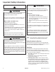
Important Safety Information Recognize this symbol as a safety precaution. ! ! ! Due to the nature of cooking, fires can occur as a result of overcooking or excessive grease. Although a fire is unlikely, if one occurs proceed as follows: WARNING If the information in this manual is not followed exactly, a fire or explosion may result causing property damage, personal injury or death. Do not store or use gasoline or other flammable vapors or liquids in the vicinity of this or any other appliance.
Important Safety Information 4. Using lights—Use a hand flashlight when servicing ranges or checking for gas leaks. Electric switches should not be operated where leaks are suspected. This will avoid creating arcing or sparks which could ignite the gas. If electric lights are already turned on, they should not be turned off. 5. Do not smoke—Never smoke while servicing gas ranges, especially when working on piping that contains or has contained gas. 6.
Important Safety Information Baking, Broiling, and Roasting • Do not use oven area for storage. • Stand back from range when opening door of a hot oven. Hot air or steam can cause burns to hands, face, and eyes. • Do not use aluminum foil anywhere in the oven. This could result in a fire hazard and damage the range. • Use only glass cookware appropriate for use in gas ovens. • Always remove broiler pan from oven when finished broiling.
General Information This manual provides basic instructions and suggestions for handling, installing and servicing gas ranges. The directions, information, and warnings in this manual are developed from experience with, and careful testing of the product. If the unit is installed according to this manual, it will operate properly and will require minimal servicing. A unit in proper operating order ensures the consumer all the benefits provided by clean, modern gas cooking.
General Information Specifications Model Identification Refer to individual Technical Sheet for specification information. Complete enclosed registration card and promptly return. If registration card is missing: • For Amana product call 1-800-843-0304 or visit the Web Site at www.amana.com • For Maytag product call 1-800-688-9900 or visit the Web Site at www.maytag.com • For product in Canada call 1-866-587-2002 or visit the Web Site at www.maytag.
General Information Grounding ! NOTE: This appliance must be properly grounded, for personal safety. Power cord on this appliance is equipped with a threeprong grounding plug. This matches standard three-prong grounding wall receptacle to prevent possibility of electric shock from this appliance. Consumer should have wall receptacle and circuit checked by qualified electrician to verify receptacle is properly grounded.
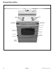
Range Description Control Oven Light Switch Surface Burners Surface Burners Surface Burner Control Knobs Surface Burner Control Knobs Door Handle Broil Burner Oven Door Oven Light and Sensor Oven Racks Door Hinge Door Hinge Bake Burner Model Number Rating Label Service/ Warming Drawer 10 16023522 ©2004 Maytag Services
Troubleshooting Procedures ! WARNING To avoid risk of electrical shock, personal injury or death; disconnect power and gas to oven before servicing, unless testing requires power and/or gas. Problem Burners will not ignite; no spark at top burner. Burner will not ignite. No spark to burner ignitors when burner knob is rotated to “LITE” position. No spark or only random spark at one ignitor. Unit continues to spark after knob is turned to OFF position. No oven operation in bake or broil.
Troubleshooting Procedures ! WARNING To avoid risk of electrical shock, personal injury or death; disconnect power and gas to oven before servicing, unless testing requires power and/or gas. Problem No gas flows to burner. Ignitor glows red. Gas flows to bake/broil burner, but burner does not light. Broil burner shuts off shortly after the start of self-clean operation. Bake and broil functions operate normally. Fan motor does not operate. 12 Possible Cause Correction Failed ignitor. ..............
Troubleshooting Procedures ! WARNING To avoid risk of electrical shock, personal injury or death; disconnect power and gas to oven before servicing, unless testing requires power and/or gas. Problem Oven light does not operate. Oven door will not unlock Oven smokes/odor first few times of usage Failure Codes Part or all of the appliance does not work ©2004 Maytag Services Possible Cause Correction Failed oven lamp ..................................... • Check lamp and replace is necessary.
Component Testing Procedures ! WARNING To avoid risk of electrical shock, personal injury or death; disconnect power and gas to oven before servicing, unless testing requires power and/or gas.
Component Testing Procedures ! WARNING To avoid risk of electrical shock, personal injury or death; disconnect power and gas to oven before servicing, unless testing requires power and/or gas. Illustration GND Component Spark module 4+0 Test Procedure Test for voltage at terminals L and N............................................... 120 VAC Spark module 2+0 CGL1100AD* Test for voltage at terminals................... 120 VAC Holder orifice Verify gas pressure (WCP) ....................
Component Testing Procedures ! WARNING To avoid risk of electrical shock, personal injury or death; disconnect power and gas to oven before servicing, unless testing requires power and/or gas. Illustration M1 Controlled Component Oven temperature adjustment M1 Controlled Temperature display M1 Controlled Clock Display M1 Controlled 24 Hour Clock M1 Controlled Factory Default M1 Controlled Twelve hour off M1 Controlled Sabbath Mode Test Procedure Press Bake pad. Enter 550 on the digit-pad.
Component Testing Procedures ! WARNING To avoid risk of electrical shock, personal injury or death; disconnect power and gas to oven before servicing, unless testing requires power and/or gas. "Quick Test" Mode for Electronic Range Control Follow procedure below to use the quick test mode. Entries must be made within 32 seconds of each other or the control will exit the quick test mode. 1. Press and hold Cancel and Broil pads for 3 seconds. 2.
Component Testing Procedures ! WARNING To avoid risk of electrical shock, personal injury or death; disconnect power and gas to oven before servicing, unless testing requires power and/or gas.
Component Testing Procedures ! WARNING To avoid risk of electrical shock, personal injury or death; disconnect power and gas to oven before servicing, unless testing requires power and/or gas. NOTES: 1 2 3 4 5 6 "Action Taken" applies as long as the condition exists. If the condition goes away, the control recovers. If there is a cook function or timer active, the function continues. The user cannot edit the function, and [Cancel] will cancel the cook mode. Flash rate: 0.2 seconds on, 0.1 second off.
Disassembly Procedures ! To avoid risk of electrical shock, personal injury, or death: disconnect electrical and gas supply before servicing. WARNING Removing and Replacing Range 1. 2. 3. 4. 5. Turn off power to the range at the circuit breaker. Turn off gas supply line to unit. Pull the range forward out of the cabinet opening. Unplug the power cord leading from unit to outlet. Replace the range using the installation instructions and anti-tip bracket(s). Maintop Assembly 1. Turn power off to unit.
Disassembly Procedures ! To avoid risk of electrical shock, personal injury, or death: disconnect electrical and gas supply before servicing. WARNING Open Burner 1. Remove maintop assembly, see "Maintop Assembly" procedure, steps 1, 4 and 5. 2. Remove clip securing burner tubing to surface valve. 3. Lift surface burner and gently move burner up and toward the rear of the range. 4. Replace and reassemble in reverse order. Oven Sensor 1. Disconnect power before servicing. 2.
Disassembly Procedures ! WARNING To avoid risk of electrical shock, personal injury, or death: disconnect electrical and gas supply before servicing. Oven Door Hinge Receiver Storage Drawer Track Removal 1. Turn off power to unit. 2. Remove oven door, see "Oven Door Removal" procedure. 3. Remove maintop assembly, see "Maintop Assembly" procedure, steps 1 through 5. 4. Remove side panel, see "Side Panel Removal" procedures. 5. Remove the top and bottom screws securing hinge assembly to the front frame.
Disassembly Procedures ! To avoid risk of electrical shock, personal injury, or death: disconnect electrical and gas supply before servicing. WARNING Frameless Door Disassembly (Large and Standard Windows) Oven Light Assembly Oven Light Bulb/Oven Light Socket NOTE: Requires removal of unit from cabinet to replace oven light socket. 1. 2. 3. 4. Turn off power to unit. Open oven door to gain access to oven light. Unscrew (counterclockwise) glass knurled dome. Unscrew (counterclockwise) oven light bulb.
Disassembly Procedures ! To avoid risk of electrical shock, personal injury, or death: disconnect electrical and gas supply before servicing.
Disassembly Procedures ! To avoid risk of electrical shock, personal injury, or death: disconnect electrical and gas supply before servicing. WARNING Door Disassembly (No Window) 1. Remove oven door, see "Oven Door Removal" procedure. 2. Place door on a protected surface. 3. Remove screws securing door handle to door panel. 4. Remove screws securing door panel to door lining and remove door liner. 5. Remove insulation from oven door. 6. Reverse procedure to reassemble oven door.
Appendix A A–1 16023522 ©2004 Maytag Services
Installation Instructions (Models CP31200AD*, CG31200AD*) -2- ©2004 Maytag Services 16023522 A– 2
Installation Instructions (Models CP31200AD*, CG31200AD*) 9,200 BTU/HR OR LESS 0 INCHES 3 INCHES (7.6 CM) MORE THAN 9,200 BTU/HR 1 INCH (2.5 CM) 3 INCHES (7.6 CM) Check the range model number plate to see if the range is approved for installation in mobile homes and/or recreational park trailers. If approved the following items are applicable.
Installation Instructions (Models CPL1100AD*, CGL1100AD*) INSTALLATION RECREATIONAL PARK TRAILERS Check the range model number plate to see if the range is approved for installation in mobile homes and/or recreational park trailers. If approved the following items are applicable. The installation of a range designed for recreational park trailers must conform with state or other codes or, in the absence of such codes, with the Standard for Recreational Park Trailers, ANSI A119.5-latest addition.
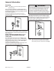
Installation Instructions (Models CPL1100AD*, CGL1100AD*) INSTALLATION DRAWINGS BACKGUARD INSTALLATION (if not installed) The backguard fits on the range as shown in figure 1 and is secured with a bracket, 2 bolts and nuts on each side. DISCONNECT ELECTRICAL POWER TO AVOID SHOCK HAZARD. Set the backguard on the rear of the range. Bolt the backguard to the end panel flanges.
Installation Instructions (Model LPR1115AD*) :$51,1* 7+,6 352'8&7 6+28/' 127 %( ,167$//(' %(/2: $ 9(17,/$7,21 7<3( +22' 6<67(0 7+$7 ',5(&76 $,5 ,1 $ '2:1:$5' ',5(&7,21 6(( ),*85( 7+(6( 6<67(06 0$< &$86( ,*1,7,21 $1' &20%867,21 352%/(06 :,7+ 7+( *$6 %851(56 5(68/7,1* ,1 3(5621$/ ,1-85< $1' 0$< $))(&7 7+( &22.,1* 3(5)250$1&( 2) 7+( 81,7 127( 7+( ),*85( 0$< 127 $&&85$7(/< 5(35(6(17 <285 5$1*( 25 &22.723 +2:(9(5 7+,6 :$51,1* $33/,(6 72 $// *$6 &22.
Installation Instructions (Model LPR1115AD*) 9,200 BTU/HR OR LESS 0 INCHES 3 INCHES (7.6 CM) MORE THAN 9,200 BTU/HR 1 INCH (2.5 CM) 3 INCHES (7.6 CM) Check the range model number plate to see if the range is approved for installation in mobile homes and/or recreational park trailers. If approved the following items are applicable.
Installation Instructions (All models except CPL1100AD*, CGL1100AD*, CP31200AD*, CG31200AD*, LPR1115AD*) -2©2004 Maytag Services 16023522 A– 8
Installation Instructions (All models except CPL1100AD*, CGL1100AD*, CP31200AD*, CG31200AD*, LPR1115AD*) 9,200 BTU/HR OR LESS 0 INCHES 3 INCHES (7.6 CM) MORE THAN 9,200 BTU/HR 1 INCH (2.5 CM) 3 INCHES (7.6 CM) Check the range model number plate to see if the range is approved for installation in mobile homes and/or recreational park trailers.
Installation Instructions (All models except CPL1100AD*, CGL1100AD*, CP31200AD*, CG31200AD*, LPR1115AD*) h. Apply a non-corrosive leak detection fluid to all joints and fittings in the gas connection between the supply line shut-off valve and the range. Include gas fittings and joints in the range if connections were disturbed during installation. Check for leaks! Bubbles appearing around fittings and connections will indicate a leak.
Installation Instructions (All models except CPL1100AD*, CGL1100AD*, CP31200AD*, CG31200AD*, LPR1115AD*) !" #$%'!* +, !" '-!% /02,%3#*% !" 24*#4 /02,%3#*% -- !" 24*#4 +-6#, The approximate height of the flame at the high or full-on position is shown below. (See figure 6) Purge all air from supply system by turning on one top burner valve. Then turn off valve and adjust top pilot flame using adjusting screw “A” (figure 6) so that flame is even with top of flash tube.
Installation Instructions (All models except CPL1100AD*, CGL1100AD*, CP31200AD*, CG31200AD*, LPR1115AD*) '4 72%%#4 #3!6'*5 #+-#/ 24*#4 !4 /02,%3#*% #46'$# 6#* 24*#4 a. The approximate length of the flame of oven burner is a 1/2 inch distinct inner blue flame, figure 8. 4 Mark ignitor location relative to main top with pencil. This mark on the main top is used as a reference point when replacing the burner assembly to insure that the burner is tightened to its original position.
Appendix B B–1 16023522 ©2004 Maytag Services
Use Instructions ©2004 Maytag Services (Models CP/CG31200AD*, CPL1100AD*, CGL1100AD*) 16023522 B–2
Use Instructions B–3 (Models CP/CG31200AD*, CPL1100AD*, CGL1100AD*) 16023522 ©2004 Maytag Services
Use Instructions (Models CPR1100AD*, CGR1110AD*, CGL1100AD*, CGR1415AD*, CGR1425AD*, CGR3725AD*, CP31200AD*, CG31200AD*, CG31400AD*, CP31600AD*, CG31600AD*, CG34800AD*) Surface Cooking High: Use to bring liquid to a boil, or reach pressure in a pressure cooker. Always reduce setting to a lower heat when liquids begin to boil or foods begin to cook. Low: Use to simmer foods, keep foods warm and melt chocolate or butter. Some cooking may take place on the Low setting if the pan is covered.
Use Instructions (Models CPR1100AD*, CGR1110AD*, CGL1100AD*, CGR1415AD*, CGR1425AD*, CGR3725AD*, CP31200AD*, CG31200AD*, CG31400AD*, CP31600AD*, CG31600AD*, CG34800AD*) Oven Cooking Manual Clean Oven Control (select models) A B C D E F NOTE: The display will show 12:00 when the appliance is first connected to power or if power is interrupted. The Bake and Broil indicators light when function is pressed. 2. Set the correct time of day using the ▲ or ▼ pads.
Use Instructions (Models CPR1100AD*, CGR1110AD*, CGL1100AD*, CGR1415AD*, CGR1425AD*, CGR3725AD*, CP31200AD*, CG31200AD*, CG31400AD*, CP31600AD*, CG31600AD*, CG34800AD*) Oven Cooking Self-Clean Oven Control (select models) A B E F G H C D I J The control panel is designed for ease in programming. The display window on the control shows time of day, timer and oven functions. Control panel shown includes model specific features. (Styling may vary depending on model.
Use Instructions (Models AGR4400AD*, AGR4412AD*, AGR5712AD*, MGR4451AD*, MGR4452AD*, MGR5751AD*, MGR5752AD*, PGR4420LD*, PGR5720LD*) Surface Cooking High: Use to bring liquid to a boil, or reach pressure in a pressure cooker. Always reduce setting to a lower heat when liquids begin to boil or foods begin to cook. Low: Use to simmer foods, keep foods warm and melt chocolate or butter. Some cooking may take place on the Low setting if the pan is covered.
Use Instructions (Models AGR4400AD*, AGR4412AD*, AGR5712AD*, MGR4451AD*, MGR4452AD*, MGR5751AD*, MGR5752AD*, PGR4420LD*, PGR5720LD*) Oven Cooking Manual Clean Oven Control (select models) A B C D E F NOTE: The display will show 12:00 when the appliance is first connected to power or if power is interrupted. The Bake and Broil indicators light when function is pressed. 2. Set the correct time of day using the ▲ or ▼ pads. If the ▲ or ▼ pad is not pressed within 30 seconds, the program will cancel.
Use Instructions (Models AGR4400AD*, AGR4412AD*, AGR5712AD*, MGR4451AD*, MGR4452AD*, MGR5751AD*, MGR5752AD*, PGR4420LD*, PGR5720LD*) Oven Cooking Self-Clean Oven Control (select models) A B E F G H C D I J The control panel is designed for ease in programming. The display window on the control shows time of day, timer and oven functions. Control panel shown includes model specific features. (Styling may vary depending on model.) A Broil Use for broiling and top browning.
Care and Cleaning Care & Cleaning Cleaning Procedures CAUTION • Be sure appliance is off and all parts are cool before handling or cleaning. This is to avoid damage and possible burns. • To prevent staining or discoloration, clean appliance after each use. • If a part is removed, be sure it is correctly replaced. * Brand names are registered trademarks of the respective manufacturers. ** To order call 1-877-232-6771 USA and 1-800-688-8408 Canada.
Care and Cleaning Care & Cleaning PART PROCEDURE Oven Window and Door - Glass (select models) • Avoid using excessive amounts of water which may seep under or behind glass causing staining. • Wash with soap and water. Rinse with clear water and dry. Glass cleaner can be used if sprayed on a cloth first. • Do not use abrasive materials such as scouring pads, steel wool or powdered cleaners as they will scratch glass.
Appendix C ©2004 Maytag Services 16023522 C–1
Conversion Instructions (Models CP31200AD*, CG31200AD*) *$6 &219(56,21 All ranges and cooktops are equipped with double coaxial (universal) orifices and with a convertible appliance pressure regulator. The unit model number plate states which gas it was adjusted for at the factory. To convert the unit to either Natural gas or LP gas will require adjustment of the orifice hoods, air shutters on the burners and adjustment of the appliance pressure regulator converter cap.
Conversion Instructions (Models CP31200AD*, CG31200AD*) 25,),&( &219(56,21 *+ , .+ , - a. Change the appliance pressure regulator from LP to natural setting. (See figure 12, 13 or 14). - a. Change the appliance pressure regulator from natural to LP setting. (See figure 12, 13 or 14). b. Screw the burner orifice hoods away from the pins. (See figure 15A). Approximately 1 1/2 to 2 turns. b.
Conversion Instructions (Models CPL1100AD*, CGL1100AD*) HOW TO REMOVE RANGE FOR SERVICING GAS CONVERSION General Follow these procedures to remove appliance for servicing: All ranges are equipped with fixed orifices and with a convertible appliance pressure regulator. The unit model number plate states which gas it was adjusted for at the factory.
Conversion Instructions (Model CPR1100AD*) Gas Conversion How To Remove Range For Servicing General Follow these procedures to remove appliance for servicing: 1. Shut off gas supply to appliance. All ranges are equipped with fixed orifices and with a convertible appliance pressure regulator. The unit model number plate states which gas it was adjusted for at the factory.
Conversion Instructions (Model CPR1100AD*) Orifice Conversion From Natural Gas To LP/Propane Gas: From LP/Propane Gas To Natural Gas: a. Change the appliance pressure regulator from Natural to LP setting (see figure 1). b. Adjust oven thermostat (see figure 2). 1. Remove the main top and the manifold panel. 2. With a flat blade screwdriver turn pilot flame screw and bypass screw counter- clockwise to loosen. Use pliers to remove screws. NOTE: Save all parts removed in conversion. 3.
Conversion Instructions (Model CPR1100AD*) Range Adjustments Top Section - Gas Top Pilot Adjustment Air Shutter - Oven Burner See figure 5. a. The approximate length of the flame of oven burner is a 1/2² distinct inner blue flame (see figure 7). b. Oven burner flame can be checked as follows: 1. Yellow flame on burner - open air shutter to the widest opening that will not cause the flame to lift or blow off the burner when cold. (See figure 8). 2.
Conversion Instructions % (Model LPR1115AD*) % % 9 ; < , = All ranges are equipped with fixed orifices and with a convertible appliance pressure regulator. The unit model number plate states which gas it was adjusted for at the factory.
Conversion Instructions (Models AGR5712AD*, CG34800AD*, CGR3725AD*, MGR5751AD*, MGR5752AD*, PGR5720LD*) All ranges are equipped with fixed orifices and with a convertible appliance pressure regulator. The unit model number plate states which gas it is adjusted for at the factory.
Conversion Instructions (Models AGR5712AD*, CG34800AD*, CGR3725AD*, MGR5751AD*, MGR5752AD*, PGR5720LD*) All ranges are equipped with fixed orifices and with a convertible appliance pressure regulator. The unit model number plate states which gas it is adjusted for at the factory.
Conversion Instructions (Models AGR5712AD*, CG34800AD*, CGR3725AD*, MGR5751AD*, MGR5752AD*, PGR5720LD*) 4. Remove the surface burner orifice hood with a ² (12.7 mm) socket wrench counter-clockwise. : Save all natural orifice hoods that are removed. 5. Place the corresponding orifice hood on the burner fitting according to figure 6. Turn the orifice hood clockwise by hand approximately one turn. Tighten the orifice hood clockwise with a ² socket wrench approximately 2 turns. 6.
Conversion Instructions (Models AGR4400AD*, AGR4412AD*, CG31400AD*, CG31600AD*, CGR1110AD*, CGR1415AD*, CGR1425AD*, CP31600AD*, MGR4451AD*, MGR4452AD*, PGR4420LD* ) Gas Conversion General Appliance Pressure Regulator Conversion All ranges are equipped with fixed orifices and with a convertible appliance pressure regulator. The unit model number plate states which gas it is adjusted for at the factory.
Conversion Instructions (Models AGR4400AD*, AGR4412AD*, MGR4451AD*, MGR4452AD*, PGR4420LD*, CGR1425AD*, CGR1415AD*, CGR1110AD*, CP31600AD*) Orifice Conversion To convert the unit to either natural gas or LP gas will require the exchange of orifice hoods. IMPORTANT: Save all parts removed in conversion. Oven Burner Conversion Surface Burner Conversion (Sealed Burner) Remove all oven racks. 1. Remove all grates. 2. Mark ignitor location on the main top with a pencil.
Conversion Instructions (Models AGR4400AD*, AGR4412AD*, MGR4451AD*, MGR4452AD*, PGR4420LD*, CGR1425AD*, CGR1415AD*, CGR1110AD*, CP31600AD*) To Reassemble: Replace burner assembly in main top and rotate approximately one-eighth turn clockwise using burner wrench until burner locks into position with ignitor aligned with reference mark on main top. 5. Place the corresponding orifice hood on the burner fitting according to figure 4. Turn the orifice hood clockwise by hand approximately one turn.
Conversion Instructions (Models AGR4400AD*, AGR4412AD*, MGR4451AD*, MGR4452AD*, PGR4420LD*, CGR1425AD*, CGR1415AD*, CGR1110AD*, CP31600AD*) Air Shutter a. The approximate length of the flame of oven burner is a 1/2 inch distinct inner blue flame, figure 7. c. The oven burner air shutter adjustment is the same on ranges with a gas pilot or electric ignition. d. Sealed burner adjustment.