MDG76PC (Phase 7.3 Coin Gas DSI) Installation Manual WARNING: For your safety the information in this manual must be followed to minimize the risk of fire or explosion or to prevent property damage, personal injury or death. AVERTISSEMENT: Assurez-vous de bien suivre les instructions données dans cette notice pour réduire au minimum le risque d’incendie ou d’explosion ou pour éviter tout dommage matériel, toute blessure ou la mort.
Retain This Manual In A Safe Place For Future Reference Our products embody advanced concepts in engineering, design, and safety. If this product is properly maintained, it will provide many years of safe, efficient, and trouble free operation. ONLY qualified technicians should service this equipment. OBSERVE ALL SAFETY PRECAUTIONS displayed on the equipment or specified in the installation manual included with the dryer.
IMPORTANT YOU MUST DISCONNECT AND LOCKOUT THE ELECTRIC SUPPLYAND THE GAS SUPPLY BEFORE ANY COVERS OR GUARDS ARE REMOVED FROM THE MACHINE TO ALLOW ACCESS FOR CLEANING, ADJUSTING, INSTALLATION, OR TESTING OF ANY EQUIPMENT PER OSHA (Occupational Safety and Health Administration) STANDARDS. “Caution: Label all wires prior to disconnection when servicing controls. Wiring errors can cause improper operation.” «Attention: Au moment de l’entretien des commandes, étiquetez tous les fils avant de les débrancher.
WARNING The dryer must never be operated with any of the back guards, outer tops, or service panels removed. PERSONAL INJURY OR FIRE COULD RESULT. WARNING DRYER MUST NEVER BE OPERATED WITHOUT THE LINT FILTER/SCREEN IN PLACE, EVEN IF AN EXTERNAL LINT COLLECTION SYSTEM IS USED. IMPORTANT PLEASE OBSERVE ALL SAFETY PRECAUTIONS displayed on the equipment and/or specified in the installation manual included with the dryer.
Table of Contents SECTION I IMPORTANT INFORMATION ............................................................................... 3 A. Receiving and Handling ............................................................................................................... 3 B. Safety Precautions ...................................................................................................................... 4 SECTION II SPECIFICATIONS/COMPONENT IDENTIFICATION ..................................... 6 A.
SECTION V DATA LABEL INFORMATION ............................................................................. 33 A. Data Label ............................................................................................................................... 33 SECTION VI PROCEDURE FOR FUNCTIONAL CHECK OF REPLACEMENT COMPONENTS ........................................................................................................
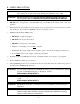
SECTION I IMPORTANT INFORMATION A. RECEIVING AND HANDLING The dryer is shipped in a protective stretch wrap cover with protective cardboard corners and top cover (or optional box) as a means of preventing damage in transit. Upon delivery, the dryer and/or packaging, and wooden skid should be visually inspected for shipping damage. If any damage whatsoever is noticed, inspect further before delivering carrier leaves. Dryers damaged in shipment: 1.
B. SAFETY PRECAUTIONS WARNING: For your safety, the information in this manual must be followed to minimize the risk of fire or explosion or to prevent property damage, personal injury, or loss of life. WARNING: The dryer must never be operated with any of the back guards, outer tops, or service panels removed. PERSONAL INJURY OR FIRE COULD RESULT. 1. DO NOT store or use gasoline or other flammable vapors and liquids in the vicinity of this or any other appliance. 2.
7. A program should be established for the inspection and cleaning of lint in the burner area, exhaust ductwork, and area around the back of the dryer. The frequency of inspection and cleaning can best be determined from experience at each location. WARNING: The collection of lint in the burner area and exhaust ductwork can create a potential fire hazard. 8. For personal safety, the dryer must be electrically grounded in accordance with local codes and/or the National Electrical Code ANSI/NFPA NO.
SECTION II SPECIFICATIONS/COMPONENT IDENTIFICATION A. SPECIFICATIONS BASKET (TUMBLER) DIAMETER 44-1/2” 113.03 cm BASKET (TUMBLER) DEPTH 24-7/8” 63.18 cm BASKET (TUMBLER) MOTOR 1 hp 0.746 kW DOOR OPENING (DIAMETER) 31-3/8” 79.7 cm BASKET (TUMBLER) VOLUME 22.4 cu.ft. 0.634 cu.m. Gas VOLTAGE AVAILABLE 120v 1ø, 60 Hz HEAT INPUT AIRFLOW 204,000 Btu/hr 51,408 kcal/hr 1,200 cfm 33.98 cmm INLET PIPE CONNECTION 3/4” F.N.P.T.
Specifications MDG76PC NOTE: Manufacturer reserves the right to make changes in specifications at any time without notice or obligation.
B. COMPONENT IDENTIFICATION 1. Dryer Front View Illus. No.
2. Dryer Rear View Illus. No. 1 2* 3 4 5 6 7 Description Heating Unit Electric Service Relay Box Basket (tumbler) Bearing Mount Assembly Idler Bearing Mount Assembly Basket (tumbler) (drive) Motor Assembly (for reversing models ONLY) Blower Motor Assembly Dryer Exhaust * Electric service connections for gas models are made in this box.
SECTION III INSTALLATION PROCEDURES Installation should be performed by competent technicians in accordance with local and state codes. In the absence of these codes, the installation must conform to applicable American National Standards: ANSI Z223.1LATEST EDITION (National Fuel Gas Code) or ANSI/NFPA NO. 70-LATEST EDITION (National Electrical Code) or in Canada, the installation must conform to applicable Canadian Standards: CAN/CGA-B149.1-M91 (Natural Gas) or CAN/CGA-B149.2-M91 (Liquid Propane [L.P.
10. The dryer must be installed with provisions for adequate combustion and make-up air supply. CAUTION: This dryer produces combustible lint and must be exhausted to the outdoors. Every 6 months, inspect the exhaust ducting and remove any lint build up. IMPORTANT: Dryer must be installed in a location/environment, which the ambient temperature remains between 40° F (4.44° C) and 130° F (54.44° C). B. UNPACKING/SETTING UP Remove protective shipping material (i.e.
c. Remove the four (4) self-taping screws on the burner box that secure it to the top of the dryer shown in the illustration below. d. Remove the two (2) self-taping screws on the back electrical box and pull through ALL associated wires from the motor to this electrical box (refer to the illustration below). e. Reverse procedure for installing top section.
C. DRYER ENCLOSURE REQUIREMENTS Bulkheads and partitions should be made of noncombustible materials and must be located a minimum of 12-inches (30.48 cm) (18-inches [45.72 cm] or more is recommended for ease of installation, maintenance, and service) above the dryer outer top, except along the front of the dryer which may be partially closed in if desired. The clearance between the bulkhead header and the dryer must be a minimum of 4-inches (10.16 cm) and must not extend more than 4-inches (10.
D. FRESH AIR SUPPLY REQUIREMENTS When the dryer is operating, it draws in room air, heats it, passes this air through the basket (tumbler), and exhausts it out of the building. Therefore, the room air must be continually replenished from the outdoors. If the make-up air is inadequate, drying time and drying efficiency will be adversely affected. Ignition problems and sail switch “fluttering” problems may result, as well as premature motor failure from overheating.
E. EXHAUST REQUIREMENTS 1. General Exhaust Ductwork Information Exhaust ductwork should be designed and installed by a qualified professional. Improperly sized ductwork will create excessive back pressure which results in slow drying, increased use of energy, overheating of the dryer, and shutdown of the burner by the airflow (sail) switches, burner hi-limits, or basket (tumbler) hi-limit thermostats. The dryer must be installed with a proper exhaust duct connection to the outside.
NOTE: As per the National Fuel Gas Code, “Exhaust ducts for type 2 clothes dryers shall be constructed of sheet metal or other noncombustible material. Such ducts shall be equivalent in strength and corrosion resistance to ducts made of galvanized sheet steel not less than 0.0195-inches (26 gauge [0.05 mm]) thick.” IMPORTANT: Exhaust back pressure measured by a manometer in the exhaust duct must be no less than 0 and must not exceed 0.3 inches (0.74 mb) of water column (W.C.).
IMPORTANT: Exhaust back pressure measured by a manometer in the exhaust duct must be no less than 0 and must not exceed 0.3 inches (0.74 mb) of water column. IMPORTANT: Minimum duct size for a dryer that is vented vertically is 12-inches (30.48 cm) for a round duct or an equivalent of 80 square inches (516.1 square centimeters). THE DUCT SIZE MUST NOT BE REDUCED ANYWHERE DOWNSTREAM OF THE DRYER.
a. Outside Ductwork Protection 1) To protect the outside end of the horizontal ductwork from the weather, a 90° elbow bent downward should be installed where the exhaust exits the building. If the ductwork travels vertically up through the roof, it should be protected from the weather by using a 180° turn to point the opening downward. In either case, allow at least twice the diameter of the duct between the duct opening and the nearest obstruction.
F. ELECTRICAL INFORMATION 1. Electrical Requirements It is your responsibility to have ALL electrical connections made by a properly licensed and competent electrician to assure that the electrical installation is adequate and conforms to local and state regulations or codes. In the absence of such codes, ALL electrical connections, materials, and workmanship must conform to the applicable requirements of the National Electrical Code ANSI/NFPA NO.
2. Electrical Service Specifications M DG76PC (Gas) ELECTRICAL SERVICE SPECIFICATIONS (PER DRYER) NOTES: A. When fuses are used they must be dual element, time delay, current limiting, class RK1 or RK5 ONLY. Calculate/determine correct fuse value, by applying either local and/or National Electrical Codes to listed appliance amp draw data. B. Circuit breakers are thermal-magnetic (industrial) motor curve type ONLY.
3. Grounding A ground (earth) connection must be provided and installed in accordance with state and local codes. In the absence of these codes, grounding must conform to applicable requirements of the National Electrical Code ANSI/NFPA NO. 70-LATEST EDITION, or in Canada, the Canadian Electrical Codes Parts 1 & 2 CSA C22.1-1990 or LATEST EDITION. The ground connection may be to a proven earth ground at the location service panel.
SINGLE-PHASE (1Ø) ELECTRICAL CONNECTION LEADS Black + Positive White Neutral Green Ground or L2 If local codes permit, power to the dryer can be made by the use of a flexible U.L. listed power cord/pigtail (wire size must conform to rating of dryer), or the dryer can be hard wired directly to the service breaker panel. In both cases, a strain relief must be installed where the wiring enters the dryer. NOTE: A CIRCUIT SERVICING EACH DRYER MUST BE PROVIDED.
G. GAS INFORMATION It is your responsibility to have ALL plumbing connections made by a qualified professional to assure that the gas plumbing installation is adequate and conforms to local and state regulations or codes. In the absence of such codes, ALL plumbing connections, materials, and workmanship must conform to the applicable requirements of the National Fuel Gas Code ANSI Z223.1-LATEST EDITION, or in Canada, the Canadian Installation Codes CAN/CGA-B149.1-M91 (Natural Gas) or CAN/CGA-B149.
2. Technical Gas Data a. Gas Specifications TYPE OF GAS NATURAL Manifold Pressure* In-Line Pressure LIQUID PROPANE 3.5 inches W.C. 8.7 mb 10.5 inches W.C. 26.1 mb 6.0 - 12.0 inches W.C. 14.92 - 29.9 mb 11.0 inches W.C. 27.4 mb Shaded areas are stated in metric equivalents * Measured at gas valve pressure tap when the gas valve is on. b. Gas Connections Inlet connection ---- 3/4” N.P.T. Inlet supply size ---- 3/4” N.P.T.
3. Piping/Connections ALL components/materials must conform to National Fuel Gas Code Specifications ANSI Z223.1-LATEST EDITION, or in Canada, CAN/CGA-B149.1-M91 (Natural Gas) or CAN/CGA-B149.2-M91 (Liquid Propane [L.P.] Gas) or LATEST EDITION (for General Installation and Gas Plumbing), as well as local codes and ordinances and must be done by a qualified professional.
Consistent gas pressure is essential at ALL gas connections. It is recommended that a 3/4-inch (19.050 mm) pipe gas loop be installed in the supply line servicing a bank of dryers. An in-line pressure regulator must be installed in the gas supply line (header) if the (natural) gas pressure exceeds 12.0 inches (29.9 mb) of water column (W.C.) pressure. NOTE: A water column test pressure of 3.5 inches (8.7 mb) for natural gas and 10.5 inches (26.1 mb) for liquid propane (L.P.
H. PREPARATION FOR OPERATION/START-UP The following items should be checked before attempting to operate the dryer: 1. Read ALL “CAUTION,” “WARNING,” and “DIRECTION” labels attached to the dryer. 2. Check incoming supply voltage to be sure that it is the same as indicated on the dryer data label affixed to the left side panel area behind the top control (access) door. 3. GAS MODELS - check to assure that the dryer is connected to the type of heat/gas indicated on the dryer data label. 4.
I. PREOPERATIONAL TESTS ALL dryers are thoroughly tested and inspected before leaving the factory. However, a preoperational test should be performed before the dryer is publicly used. It is possible that adjustments have changed in transit or due to marginal location (installation) conditions. 1. Turn on electric power to the dryer. a. Open ALL shutoff valves. 2. Refer to the Operating Instructions for starting your particular model dryer. a.
NOTE: To check for proper sail switch operation, open the main door and while holding main door switch plunger in, start dryer. Dryer should start but heat circuit should not be activated (on). If the heat system is activated, the sail switch is improperly adjusted and must be adjusted by bending the actuator arm of the sail switch toward the burner box. If the actuator arm is bent too far toward the burner box of the dryer, the dryer may not have heat when needed.
6. Check to insure that ALL setscrews (i.e., basket [tumbler] drive, idler, etc.) are tight. J. PREOPERATIONAL INSTRUCTIONS 1. COIN MODELS a. Microprocessor Controller (computer) 1) When the microprocessor controller (computer) is in the ready state, the liquid crystal display (L.C.D.) screen will display “Ready, Insert $XX.XX (amount) to Start.” 2) Insert coin(s). Once the correct “Amount To Start” has been inserted, the L.C.D. will display “Select Temperature.
SECTION IV ROUTINE MAINTENANCE A. CLEANING A program and/or schedule should be established for periodic inspection, cleaning, and removal of lint from various areas of the dryer, as well as throughout the ductwork system. The frequency of cleaning can best be determined from experience at each location. Maximum operating efficiency is dependent upon proper air circulation. The accumulation of lint can restrict this airflow.
90 DAYS 1. Remove lint from around basket (tumbler), drive motors, and surrounding areas. 2. Remove lint from gas valve burner area with a dusting brush or vacuum cleaner attachment. 3. Clean any lint accumulation in and around both the blower and drive motor casing openings. EVERY 6 MONTHS Inspect and remove lint accumulation in customer furnished exhaust ductwork system and from dryer’s internal exhaust ducting. NOTE: THE ACCUMULATION OF LINT IN THE EXHAUST DUCTWORK CAN CREATE A POTENTIAL FIRE HAZARD.
SECTION V DATA LABEL INFORMATION A. DATA LABEL Contact Maytag Co. When contacting the Maytag dealer, or the Maytag Co., certain information is required to insure proper service/ parts information. This information is on the data label affixed to the left side panel area behind the top control (access) door. When contacting Maytag Co., please have the model number and serial number readily available.
THE DATA LABEL 1. MODEL NUMBER The model number is an Maytag Company number, which describes the size of the dryer and the type of heat (gas, electric, or steam). 2. SERIAL NUMBER The serial number allows Maytag to gather information on your particular dryer. 3. MANUFACTURING CODE NUMBER The manufacturing code number is a number issued by the manufacturer, which describes ALL possible options on your particular model. 4.
SECTION VI PROCEDURE FOR FUNCTIONAL CHECK OF REPLACEMENT COMPONENTS 1. Microprocessor Controller (Computer) Board a. Phase 7 Coin Models 1) Upon completing installation of the replacement microprocessor controller (computer) board, reestablish power to the dryer. 2) Start the drying cycle by pressing any temperature selection keys (HI, LO, PP). 3) Verify that the applicable indicator lights on the microprocessor controller (computer) board are lit. (Refer to the illustration below.
2. For Models With Johnson Controls Direct Spark Ignition (DSI) Module (G760) Theory Of Operation: Start the drying cycle. When the gas burner ignites within the chosen trial for ignition time (6-seconds), the flame sensor detects gas burner flame and signals the DSI module to keep the gas valve open...as long as there is a call for heat. The DSI module will “LOCKOUT” if the gas burner flame is not sensed at the end of the trial for ignition period.
Part No.