
user manual

7
Natural Gas:
This dryer is factory adjusted for use with NATURAL GAS (G20),
and no further adjustment should be required at installation.
L.P. Gas:
This dryer is also certified for use with L.P. (propane or butane)
gases with appropriate conversion. No attempt shall be made to
convert the appliance from the gas specified on the model/serial
rating plate for use with a different gas without consulting the
serving gas supplier.
Conversion must be done by a competent service technician.
Gas conversion kit, part number W10233219, is available for
purchase from your dealer. Full instructions are supplied with
the kit.
Natural gas (France/Belgium):
This dryer is also certified for France/Belgium for use with
G20/G25 gases (20 mbar/25 mbar) with appropriate conversion.
No attempt should be made to convert this appliance from the
gas specified on the gas rating label for use with a different gas
without consulting the serving gas supplier. Gas conversion must
be done by a qualified gas service technician. Conversion kit, part
number (W10181947) is available for purchase from your dealer.
Full instructions are supplied with the kit.
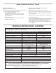
Supply line requirements:
Provide a rigid gas supply line to the dryer location. It should be
minimum 12.5 mm (1/2") ID. When acceptable to the gas supplier
and local codes, 10 mm (3/8") ID rigid supply line may be used
for lengths under 6.1 m (20'). Pipe-joint compounds resistant to
the action of L.P. gas must be used.
Gas connection to the dryer itself should be made by means of
a flexible gas hose suitable for the appliance and gas category
in accordance with national installation regulations. If in doubt,
contact the gas supplier. It should be minimum 10 mm (3/8") ID.
A means of restraint should be used between the appliance and
the wall to prevent straining of the rigid gas supply when the
appliance is moved. An appropriate length of chain and a wall
hook is recommended.
The dryer gas inlet connection is a 3/8" NPT thread. An adapter is
supplied for conversion to standard ISO.228-1 thread (3/8" BSP).
Check for leaks by using an approved noncorrosive leak-
detection solution. Bubbles will show a leak. Correct any leak
found. A pressure measurement tapping is provided on the
gas valve within the dryer, accessible after removal of the lower
front panel.
The dryer must be disconnected from the gas supply piping
system during any pressure testing of that system.
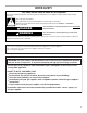
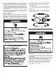
WARNING
Fire Hazard
Use a heavy metal vent.
D
o not use a plastic vent.
Do not use a metal foil vent.
Failure to follow these instructions can result in death
or fire.
Venting Requirements
WARNING: To reduce the risk of fire, this dryer MUST BE
EXHAUSTED OUTDOORS.
■ Following these venting requirements will minimise ducting
air noise.
■ Gas dryers should only be installed in a room if the room
meets the appropriate ventilation requirements specified
in the national installation regulations. Make sure the room
containing the dryer has an adequate air supply for gas
combustion and drying operation. A window or equivalent
means of ventilation must be opened in the room when the
dryer is in use (an equivalent form of opening includes an
adjustable louver, hinged panel, or other means of ventilation
that opens directly to outside air). Adequate ventilation has to
be provided to avoid the backflow of gases into the room from
other fuel-burning appliances, including open fires (i.e. available
airflow into the room should match airflow out from the room).
■ The design of the flue system should be such that any condensate
formed when operating the dryer from cold shall either be retained
and subsequently re-evaporated or discharged. Following these
instructions should adequately meet this requirement.
■ The dryer vent must not be discharged into a flue which
is used for exhausting fumes from appliances burning gas or
other fuels, chimney, wall, ceiling, or a concealed space of a
building, or any other vent used for venting.
■ Do not use an exhaust hood with a magnetic latch.
■ Do not install flexible metal vent in enclosed walls, ceilings,
or floors.
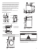
■ 102 mm (4") heavy metal vent and clamps must be used.
■ Use clamps to seal all joints. Vent must not be connected or
secured with screws or other fastening devices which extend
into the interior of the vent and catch lint. Do not use duct tape.
IMPORTANT: Observe all governing codes and ordinances.
Use a heavy metal vent. Do not use plastic or metal foil vent.
Rigid metal vent is recommended to avoid crushing and kinking.
Flexible metal vent must be fully extended and supported when
the dryer is in its final position. Remove excess flexible metal vent
to avoid sagging and kinking that will result in reduced airflow
and poor performance.
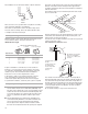
An exhaust hood should cap the vent to keep rodents and
insects from entering the building.
Exhaust hood must be at least 305 mm (12") from the ground
or any object that may be in the path of the exhaust (such as
flowers, rocks, or bushes).
If using an existing vent system, clean lint from the entire length
of the system and make sure exhaust hood is not plugged with
lint. Replace any plastic or metal foil vent with rigid metal or
flexible metal vent.