Service This manual is to be used by qualified appliance technicians only. Maytag does not assume any responsibility for property damage or personal injury for improper service procedures done by an unqualified person.
Important Information Important Notices for Servicers and Consumers Maytag will not be responsible for personal injury or property damage from improper service procedures. Pride and workmanship go into every product to provide our customers with quality products. It is possible, however, that during its lifetime a product may require service.
Important Information .................................................... 2 Important Safety Information ......................................... 4 General Information Model Identification .................................................... 8 Serial Label Location ................................................. 8 Model Nomenclature .................................................. 9 Troubleshooting Troubleshooting General Symptoms .........................
Important Safety Information ! WARNING To avoid risk of fire, electric shock, serious injury, or death when using your dryer, follow these basic precautions: 1. Read all instructions before using dryer. 2. Install dryer according to Installation Instructions. Refer to the Grounding Instructions in the Installation Instructions for proper grounding of the dryer. 3.
Important Safety Information Electrical Service Information ! WARNING To reduce the risk of fire and exposure to combustion gases, the dryer MUST be exhausted to the outdoors. DO NOT exhaust dryer air into a window well, gas vent, chimney or enclosed, unventilated area, such as an attic, wall, ceiling, crawl space under a building or concealed space of a building.
Important Safety Information Gas Connection Information ! WARNING To avoid death, personal injury or property damage, from fire or explosion, information in this manual must be followed exactly. Do not store or use gasoline or other flammable vapors and liquids in the vicinity of this or any other appliance. WHAT TO DO IF YOU SMELL GAS • Do not try to light any appliance. • Do not touch any electrical switch; do not use any phone in your building.
Important Safety Information ©2006 Maytag Services 16026315 7
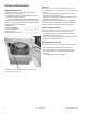
General Information Service Model Identification Complete registration card and promptly return. If registration card is missing: • For Maytag product call 1-800-688-9900 or visit the Web Site at www.maytag.com • For product in Canada call 1-800-688-2002 or visit the Web Sites at www.maytag.com or www.jennair.com When contacting provide product information located on rating plate.
General Information Troubleshooting Guide is located inside the Control Console, see Control Console Access/ Facia Removal Procedure.
Troubleshooting Procedures Due to possibility of personal injury or property damage, always contact an authorized technician for servicing or repair of this unit. ! WARNING To avoid risk of electrical shock, personal injury or death; disconnect power and shut off gas to unit before servicing, unless testing requires power. Will not start or run: • All wires are hooked up to their corresponding terminals. • Dryer is plugged in. • Blown fuse or circuit breaker. • Door switch functional...door closed.
Troubleshooting Procedures Due to possibility of personal injury or property damage, always contact an authorized technician for servicing or repair of this unit. ! WARNING To avoid risk of electrical shock, personal injury or death; disconnect power and shut off gas to unit before servicing, unless testing requires power. ENTER SERVICE MODE Rotate the Cycle Selector Knob to the “Power Off” position and press knob. (All LED’s will be off).
Troubleshooting Procedures Due to possibility of personal injury or property damage, always contact an authorized technician for servicing or repair of this unit. ! WARNING To avoid risk of electrical shock, personal injury or death; disconnect power and shut off gas to unit before servicing, unless testing requires power. CONSOLE SWITCH TEST Enter Service Mode then set Cycle Selection Knob to “Wrinkle Prevent” and press knob. • • Power Off LED blinks. Pause and Wrinkle Prevent LED’s are illuminated.
Troubleshooting Procedures Due to possibility of personal injury or property damage, always contact an authorized technician for servicing or repair of this unit.
Component Testing Information ! WARNING To avoid risk of electrical shock, personal injury or death; disconnect power and shut off gas to unit before servicing, unless testing requires power. Illustration Component Thermistor Door Switch Light Motor Test Procedure Unplug harness connector and test from wire insertion side. Pin #1 PK and Pin #11 PK of PS5....... Door open terminals............................ Infinity Door closed terminals..........................
Component Testing Information ! WARNING To avoid risk of electrical shock, personal injury or death; disconnect power and shut off gas to unit before servicing, unless testing requires power. Illustration Component Sensor Bars Test Procedure Unplug harness connector and test from wire insertion side. Short sensor bar. Results Pin #3 BU to Pin # 7 BU of PS5........... Less than 1 ohm Unplug connectors and test sensor terminals..............................................
Disassembly Procedures ! To avoid risk of electrical shock, personal injury or death; disconnect power to unit and shut off gas supply before performing any disassembly procedure. WARNING Control Console Access / Facia Removal NOTE: Wear an Anti-Static Wrist Strap and ground yourself before working with Electronic Control Boards. Always handle boards by the edge and don’t touch discreet components. 3. Remove wiring harness connectors from PC Board. 1. Disconnect power supply to unit. 2.
Disassembly Procedures ! To avoid risk of electrical shock, personal injury or death; disconnect power to unit and shut off gas supply before performing any disassembly procedure. WARNING Cycle Selector Knob (CSK) Removal 1. Disconnect power supply to unit. 2. Access Control Console, see “Control Console Access / Facia Removal” procedure. 3. Remove PC Board. 4. Lift locking tab on CSK and rotate switch to remove. Top Cover / Door Switch / Front Panel / Gasket Removal 1. Disconnect power supply to unit.
Disassembly Procedures ! To avoid risk of electrical shock, personal injury or death; disconnect power to unit and shut off gas supply before performing any disassembly procedure. WARNING 5. Remove two screws, 1 each side, from the back flange of the Front Panel. Door Reversal / Disassembly 1. Disconnect power supply to unit. 2. Remove four screws on Door Hinge. 6. Tip Front Panel back and remove. Rotate Front Panel to the back side and remove gasket. 3.
Disassembly Procedures ! To avoid risk of electrical shock, personal injury or death; disconnect power to unit and shut off gas supply before performing any disassembly procedure. WARNING 4. To switch Door Hinge side, remove screws around the perimeter of the Door Panel. Rotate Door Panel 180 degrees and move Door Strike to opposite side of Door. Reinstall screws. Reinstall Door. Continue to next step for complete Door disassembly. Light Removal 5.
Disassembly Procedures ! WARNING Motor/Blower/Thermistor/Thermostat Removal 1. 2. 3. 4. Disconnect power supply to unit. Remove Top Cover. Remove Front Panel. Disconnect wiring from Moisture Sensor. To avoid risk of electrical shock, personal injury or death; disconnect power to unit and shut off gas supply before performing any disassembly procedure. 6. To remove Thermistor or Thermostat, disconnect wiring from component(s) and remove retaining screws. 5.
Disassembly Procedures ! WARNING 8. Remove Blower Cover Panel. 9. Disconnect Motor Harness connector from Motor. 10. Rotate Blower Assembly as shown to remove from dryer. To avoid risk of electrical shock, personal injury or death; disconnect power to unit and shut off gas supply before performing any disassembly procedure. 11. Remove Blower Wheel by placing a wrench on the rear of the Motor shaft and the nut on the Blower Wheel. Rotate counterclockwise to loosen. 12.
Disassembly Procedures ! To avoid risk of electrical shock, personal injury or death; disconnect power to unit and shut off gas supply before performing any disassembly procedure. WARNING Drum Removal / Roller / Glide Access 1. Disconnect power supply to unit. 2. Remove Top Cover and Front Panel, see “Top Cover / Door Switch / Front Panel / Gasket Removal” procedure. 3. Remove wires from light, see “Light Removal” procedure steps 3 - 4. 4. Remove four screws on Front Bulkhead. 22 5.
Disassembly Procedures ! To avoid risk of electrical shock, personal injury or death; disconnect power to unit and shut off gas supply before performing any disassembly procedure. WARNING Heater Removal Drum Baffle Removal 1. Disconnect power supply to unit. 2. Remove Top Cover and Front Panel, see “Top Cover / Door Switch / Front Panel / Gasket Removal” procedure. 3. Remove Belt from Idler Pulley. 4. Remove Drum. 5. Remove two screws securing Heater Assembly to rear bulkhead. 1.
Disassembly Procedures ! To avoid risk of electrical shock, personal injury or death; disconnect power to unit and shut off gas supply before performing any disassembly procedure. WARNING NOTE: The Igniter Bar is fragile. Be careful not to damage Igniter when removing Burner Assembly. ! WARNING To avoid risk of personal injury or death; shut off gas supply to unit before servicing Burner Assembly. Gas Model Disassembly Igniter Removal 1. 2. 3. 4. 5. Disconnect power supply to unit. Remove Top Cover.
Appendix A ©2006 Maytag Services 16026315 A–1
NOTES A-2 16026315 ©2006 Maytag Services
® Installation Instructions Electric Dryer Keep instructions for future reference. Be sure manual stays with dryer.
CONNECT DRYER TO EXHAUST SYSTEM 2 Secure all joints with clamps or duct tape. DO NOT use sheet metal screws or other fastening means which extend into the duct to attach exhaust pipe joints. They could catch lint and reduce the efficiency of the exhaust system. IMPORTANT: Keep exhaust duct as short as possible. Be sure old ducts are clean before installing your new dryer. Exhaust System Materials Use Exhaust duct must be four inches (10.2 cm) in diameter without obstructions.
CONNECT ELECTRICAL CORD 3 3-wire or 4-wire Plug Connection • White wire to Neutral terminal. • 4-wire Plug Only—Remove ground screw and detach ground wire from bulkhead. Attach power cord ground (green) wire to rear bulkhead using ground screw. Attach free ground wire, previously attached with ground screw, with white wire to the neutral (center) terminal on the terminal block. Four-wire cord is required for mobile homes or where codes do not permit grounding through neutral. 1.
Important Safety Information About Ground Wires In the event of an electrical short circuit, a ground wire reduces the risk of electric shock by providing an escape wire for the electric current. Standard accepted color coding for ground wires is green or green with a yellow stripe. Grounding wires and wires colored like grounding wires are NOT to be used as current carrying conductors.
Installation Requirements Before You Install… Consider Description Location Use dimensions shown in manual to determine space needed for installation. Place dryer on a solid floor in an area with an adequate air supply. A closet door must have a supply air vent of 80 sq. in. (517 sq. cm) minimum. Leveling legs can be adjusted from inside the dryer with a 1⁄4" driver. All four legs must rest firmly on the floor so the weight of the dryer is evenly distributed. The dryer must not rock.
*36" (91,4 cm) *43" (109,2 cm) Dryer Dimensions and Minimum Clearances 7.7" (19,6 cm) 4.0" (10,2 cm) 15.4" (39,1 cm) 4.0" (10,2 cm) 23.5" (59,7 cm) .4" (1,1 cm) 28" (71,1 cm) 26.9" (68,3 cm) *With leveling legs turned fully into base FRONT VIEW (w/o Closet Door) SIDE VIEW FRONT VIEW (Closet Door) 3" (7,6 cm) Closet Door 12" (30,5 cm) 2" (5,1 cm) Centered air openings minimum 40 sq. in. (260 sq. cm) each 0" (0 cm) 12" (30,5 cm) Min.
® Installation Instructions Gas Dryer Keep instructions for future reference. Be sure manual stays with dryer. You'll Need a Few Things Before You Begin Duct Tape Stainless Steel or Hard Pipe Gas Connector Wrench Teflon Tape or Joint Compound Kits are available at extra cost through your Maytag dealer or Maytag Customer Assistance at 1-800-688-9900 USA 1-800-688-2002 Canada 1-800-688-2080 TTY USA Only Screw Drivers Directional Exhaust Kit DK1 Sales Accessory (Directional Exhaust Kit #528P3).
CONNECT DRYER TO EXHAUST SYSTEM 2 Secure all joints with clamps or duct tape. DO NOT use sheet metal screws or other fastening means which extend into the duct to attach exhaust pipe joints. They could catch lint and reduce the efficiency of the exhaust system. IMPORTANT: Keep exhaust duct as short as possible. Be sure old ducts are clean before installing your new dryer.
CONNECT GAS SUPPLY 3 L.P./Propane DO NOT connect dryer to L.P./Propane gas service without converting the gas valve. An LPK1 Sales Accessory L.P./Propane Gas Conversion Kit 649P3 must be installed. Connect gas supply to dryer using a new stainless steel flexible connector or hard pipe (check local codes) according to illustration. Test for leaks and check burner flame after gas supply is connected. See Checking Burner Flame section on back page.
Important Safety Information About Ground Wires Grounding Instructions In the event of an electrical short circuit, a ground wire reduces the risk of electric shock by providing an escape wire for the electric current. Dryer must be grounded. Dryer is equipped with a cord having a grounding conductor and a 3-prong grounding plug. The three-prong grounding plug on the power cord should be plugged directly into a polarized three-slot grounded receptacle rated 110/120V AC (alternating current) 15 Amps.
Installation Requirements Before You Install… Consider Description Location Use dimensions shown in manual to determine space needed for installation. Place dryer on a solid floor in an area with an adequate air supply. A closet door must have a supply air vent of 80 sq. in. (517 sq. cm) minimum. No other fuel burning appliance should be installed in the same closet with the dryer. Dryer must not be installed or stored in an area where it will be exposed to water and/or weather.
Installation Checks and Adjustments Checking Burner Flame To view the burner flame, remove the lower front panel of the dryer. *43" (109,2 cm) *36" (91,4 cm) 7.7" (19,6 cm) 4.0" (10,2 cm) WARNING 15.4" (39,1 cm) 4.0" (10,2 cm) 28" (71,1 cm) 23.5" (59,7 cm) 2.8" 2.3" (7 cm) 26.9" (6 cm) (68,3 cm) .
Appendix B The Use and Care information provided in this service manual is representative of a limited number of models. Reference the customer’s Use and Care literature included with the product, order a copy, or consult the manufacturer’s website for the specific model (www.maytag.com).
B-2 16026315 ©2006 Maytag Services
MD-1 Use & Care Guide Table of Contents Important Safety Instructions . . . . . . . . . . . . . . . .1-2 Reversing the Door . . . . . . . . . . 12 Dryer Exhaust Tips . . . . . . . . . . 13 Using the Controls Auto Dry Models . . . . . . . . . . . . . .3-4 Sensor Models . . . . . . . . . . . . . . . .5-6 Electronic Controls . . . . . . . . . . . .7-9 Troubleshooting . . . . . . . . . . . . . 14 Operating Tips . . . . . . . . . . . . . . 10 Accessories . . . . . . . . . . . . . . . . 10 Care & Cleaning .
1 B-4 16026315 ©2006 Maytag Services
2 ©2006 Maytag Services 16026315 B-5
3 B-6 16026315 ©2006 Maytag Services
4 ©2006 Maytag Services 16026315 B-7
5 B-8 16026315 ©2006 Maytag Services
6 ©2006 Maytag Services 16026315 B-9
7 B-10 16026315 ©2006 Maytag Services
8 ©2006 Maytag Services 16026315 B-11
9 B-12 16026315 ©2006 Maytag Services
10 ©2006 Maytag Services 16026315 B-13
11 B-14 16026315 ©2006 Maytag Services
12 ©2006 Maytag Services 16026315 B-15
13 B-16 16026315 ©2006 Maytag Services
14 ©2006 Maytag Services 16026315 B-17
B-18 16026315 ©2006 Maytag Services
Dryer ND-1 Use & Care Guide Important Safety Instructions . . . . . . . . 1-2 Using the Controls Auto Dry Models . . . . . . . . . . . . . . . . . . . . .3-4 Electronic Controls . . . . . . . . . . . . . . . . . . . .5-7 Operating Tips . . . . . . . . . . . . . . . . . . . . . . . 8 Accessories . . . . . . . . . . . . . . . . . . . . . . . . . 8 Care & Cleaning . . . . . . . . . . . . . . . . . . . . . . 9 Reversing the Door . . . . . . . . . . . . . . . . . . 10 Dryer Exhaust Tips . . . . . . . . . . . .
1 B-20 16026315 ©2006 Maytag Services
2 ©2006 Maytag Services 16026315 B-21
3 B-22 16026315 ©2006 Maytag Services
4 ©2006 Maytag Services 16026315 B-23
5 B-24 16026315 ©2006 Maytag Services
6 ©2006 Maytag Services 16026315 B-25
7 B-26 16026315 ©2006 Maytag Services
8 ©2006 Maytag Services 16026315 B-27
9 B-28 16026315 ©2006 Maytag Services
10 ©2006 Maytag Services 16026315 B-29
11 B-30 16026315 ©2006 Maytag Services
12 ©2006 Maytag Services 16026315 B-31
B-32 16026315 ©2006 Maytag Services
PDT-1 Clothes Dryer Use & Care Guide Table of Contents Important Safety Instructions . . . . . . . . . . . . . . . .1-2 Reversing the Door . . . . . . . . . . .9 Using the Controls Dryer Exhaust Tips . . . . . . . . . . .10 5 Cycles Model . . . . . . . . . . . . . . . . . . . . .3-4 6 Cycles Model . . . . . . . . . . . . . . . . . . . . .5-6 Troubleshooting . . . . . . . . . . . . 11 Operating Tips . . . . . . . . . . . . . . . 7 Accessories . . . . . . . . . . . . . . . . . 7 Care & Cleaning . . .
1 B-34 16026315 ©2006 Maytag Services
2 ©2006 Maytag Services 16026315 B-35
3 B-36 16026315 ©2006 Maytag Services
4 ©2006 Maytag Services 16026315 B-37
5 B-38 16026315 ©2006 Maytag Services
6 ©2006 Maytag Services 16026315 B-39
7 B-40 16026315 ©2006 Maytag Services
8 ©2006 Maytag Services 16026315 B-41
9 B-42 16026315 ©2006 Maytag Services
10 ©2006 Maytag Services 16026315 B-43
11 B-44 16026315 ©2006 Maytag Services