lVLAG POWER DIRECT VENT GAS WATE USER'S HEATER UIDE For Your Safety AN ODORANTIS ADDEDTO THEGAS USEDBYTHISWATERHEATER WARNING: If the information in these instructions are not followed exactly, a fire or explosion may result, causing property damage, personalinjury or death. -Do not store or use gasoline or other flammable vapors and liquids in the vicinity of this or any other appliance. -WHAT TO DO IFYOU SMELLGAS • Do not try to light any appliance.
Safety Instructions A WARNING _WARNING Improper installation, adjustment, alteration, service or mamtanance can cause DEATH, SERIOUS BODILY INJURY, OR PROPERTY DAMAGE.
Safety Instructions AWARNING AWARNING Do not install in a confined area such a closet, unless you provide ventilation air as shown in the "Locating The New Water Heater" section. Never obstruct the flow of ventilation air. If you have any doubts or questions at all, call your gas company, Failure to provide ventilation air can result in a fire or explosion and can cause DEATH, SERIOUS BODILY INJURY,OR PROPERTY DAMAGE, This water heater must not be installed directly on carpeting.
Safety Instructions AWARNING AWARNING The water heater must be properly vented to the outdoors. Never operate the water heater unless it is vented to the outdoors and has adequate air supply to avoid risks of improper operation, explosion or asphyxiation, INSULATING JACKETS: When installing an external water heater insulation jacket on a gas water heater: • DO NOT cover the temperature-pressure relief valve. • DO NOT put insulation over any part of the top of the gas water heater.
Table of Contents Customer Information ......................................................................................... .6 Pr°duct e n C ° SNeeaea Materials Needed ................................................................................................................................................................ Basic Tools ...................................................................................................................................................................
Customer Information Thank You for purchasing a Maytag water heater. Since we cannot put everything on the first few pages, READ THE ENTIRE MANUAL BEFORE ATTEMPTING TO INSTALL OR OPERATE THE WATER HEATER. • The installation must conform with the instructions in this Properly installed and maintained, it should give you years of trouble free service.
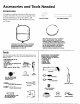
Accessoriesand Tools Needed Accessories To simplify the installation Maytag has available the installa- tion parts shown below. You may or may not need aU of these ( ABS VENTELBOW accessories depending on your type of installation. Call Maytag Customer Service at 1-800-788-8899 for an authorized installer.
Instructions for Installation Removing the Old Water Heater Turn "OFF" the gas supply to the water heater. @ _, WARNING Disconnect the vent pipe from the draft hood or blower assembly where they connect to the water heater. In most ] instaUations or other attached the vent devices pipe are canremoved.
Instructions for Installation (cont'd) TYPICAL INSTALLATION INTAKE FOR COMBUSTION AIR Vacuum Relief required ' some codes EXHAUST VENT TO OUTDOORS DISCHARGE PIPE HOT WATER OUTLET TEMPERED WATER OUTLET \\_ / _ _\_ _\_ TEMPERATUREPRESSURE RELIEF VALVE MIXING VALVE \\_ _\_ _\_ _ : GAS SUPPLY _ DISCHARGE PIPE (Do not cap or plug) PROVIDE A 6" AIR GAP BETWEEN THE END OF THE DISCHARGE PIPE AND DRAIN This appliance has been design certified as complying with American National Standard/CSA considered
Instructions for Installation (cont'd) Locating the New Water Heater ACAUTION WATER HEATERS EVENTUALLY LEAK: Installation of the water heater must be accomplished in such a manner that if the tank or any connections should leak, the flow of water will not cause damage to the structure. For this reason, it is not advisable to install the water heater in an attic or upper floor. When such locations cannot be avoided, a suitable drain pan should be installed under the water heater.
Instructions for Installation (cont'd) Locating the New Water Combustion Air and Exhaust Heater (cont'd) Whon determining the installation location for a power direct vent water heater, snow accumulation and drifting should be considered in areas where applicable. _WARNING This water heater must not be installed directly on carpeting. Carpeting must be protected by a metal or wood panel beneath the appliance extending beyond the full width and depth of the appliance by at least 3 inches (76.
Instructions for Installation VENTINGCLEARANCES (CONT'D) -_ WIRE FENCE touched accidentally, or is accessible to small children, a wire mesh chain rink fence (as shown in Figure 6) may be used. When the water heater to outlet terminal is lowventilation enough toaround be Care should be taken maintain adequate the outlet terminal. Ifa chain link fence is installed, it must "%"_, 9" min. from any overhang _ (cont'd) _.of Flue not be used as a storage area for items that may block proper ventilation.
Instructions for Installation (cont'd) Water Piping AWARNING 2. Look at the top cover of the water heater. The cold water HOTTER WATER CAN SCALD: Water heaters are intended to produce hot water. Water heated to a temperature which will satisfy clothes washing, dish washing, and other sanitizing needs can scald md permanently injure you upon contact. Some people are more likely to be permanently injured by lot water than others. These include the elderI.
Instructions for Installation (cont'd) Temperature-Pressure Relief Valve WARNING A WARNING At the time of manufacture this water heater was provided with a combination tempereture-pressures relief valve certified by a nationally recognized testing laboratory that maintains periodic inspection of production of listed equipment or materials, as meeting the requirementsfor Relief Valves and Automatic Gas Shutoff Devices for Hot Water Supply Systems, and the latest edition of ANSI Z21.
Instructions for Installation (cont'd) Filling the Water Heater ACAUTION If you are not familiar with electric codes and practices, or if Neverusethis water heaterunlessit is completelyI filled with water. Toprevent damage to the tank, you haveany doubt in your abilityto connectthe wiring to this waterheater,obtainthe serviceof a competentelectrician the tank must be filledwith water. Water must flow I from the hot water faucet before turning "ON" gas to the water heater.
Instructions for Installation (cont'd) Wiring (cont'd) USE WITHOUT POWER CORD (cont'd) 3. A standard 1/2"conduit opening has been made in the water heater junction box for the conduit connection, grounded. A green ground screw has been provided on the water heaters junction box. Connect ground wire to this location. For complete grounding details and all allowable exceptions, refer to the latest edition of the National Electrical Code. 4.
Instructions for Installation (cont'd) Venting AWARNING To insure proper venting of this gas-fired water heater, the correct vent pipe diameter must be utilized. Any additions of other gas appliances on vent with this water heater will adversely affect the operation of the water heater, _WARNING Chemicalvapor corrosionof the flue and vent systam may occurif air for combustioncontainscertain chemicalvapors.
Instructions for Installation (cont'd) Venting (cont'd) VENTING SYSTEM EXAMPLE INSTALLATIONS FOR ALL MODELS 1. The water heater requires its own (separate) venting system. The vent piping cannot under any circumstances be run downhill. 2. O_ly3"ABS Schedale 4Opiping and fittlngs are acceptable materials on the first five feet oft.he outlet vent system. 3.
Instructions for Installation (cont'd) Venting (cont'd) 3 ELBOW EXAMPLE CAULK JOINT_ _r_"_l _ __ _ ! Cementing PVC, ABS OR CPVC Pipe and Fittings Read and observe all safet_ information printed on primer, I1_ [ _AADANGER |Primer, cleaner, and cements are extremely cleaner' and cement I The vapors are harmful. They may irritate eyes and /flammable. They are harmful or fatal if swallowed. [ skin and can be absorbed through the skin. cOntaIners'PER MIN" FIVEFEET RIsE¼" t I_-.
Instructions for Installation (cont'd) Venting (cont'd) VENT PIPE SEPARATION INSTALLATION SHOWING USE OF PVC, ABS OR CPVC PIPE FOR INLET AND OUTLET VENT PIPING: The inlet and outlet vent pipes must be separated by a minimum distance of 6% inches up to 24 inches maximum. Inlet piping through any type wall. ..
Instructions for Installation (cont'd) INSTALLATION SHOWING USE OF (OPTIONAL) DELUXE HORIZONTAL VENT KIT: 3. 3" PVC, ABS, or CPVC Schedule 40 piping and fittings are acceptable materials for the inlet vent system and for the outlet vent system (after the first five feet for 75 Gal. Models only). Typical installation, AIRINTAKE 4. It cannot be connected to existing vent piping or chimney. 5. It must terminate vertically to the outdoors. 6.
Instructions for Installation (cont'd) Gas Piping _WARNING ll, WARNING Make sure the gas supplied is the same type listed on the model rating plate. The inlet gas pressure must not exceed 10.5 in. water column (2.6 kPa) for natural gas or 13 in. water column (3.2 kPa) for Propane (L.R) gas.
Instructions for Installation (cont'd) GAS PIPING WITH FLEXIBLE CONNECTOR GAS SUPPLY PIPING SHUTOFF VALVE MANUAL FLEXIBLE GAS CONNECTOR LABELED AS COMPLYING WITH ANSI STANDARDS LOOP GROUND JOINT UNION (OPTIONAL) 3 MIN. I (SEDIMENT - _I_V f _ TR2P' GAS PIPING WITH ALL BLACK IRON PIPE TO GAS CONTROL GAS SUPPLY PIPING SHUTOFF VALVE MANUAL GROUND JOINT -_ UNION _ BLACKPIPE_ I _ _(-_'_ ;_ _ _r--rl IN 3" MIN, _ _o_.
Instructions for Installation (cont'd) Installation Checklist CHECK FOR LEAKS BEFORE OPERATING: Be sure to check all your gas pipes for Ieaks before operating • Check your water heater. Use a soapy water solution, the gas fines for leaks, a. Use a soapy water solution. DO NOT using a match or open flame. b. Brush the soapy water solution test for gas leaks open flame. Check the factory gas fittings on all gas pipes, joints er is turned e. Rinse offsoapy COMBUSTION EXHAUST AIR VENTTO . soap.
Instructions for Operation This water heater is equipped with an electrically operated venting system and electronic control. For the burner to come on, the water heater thermostat BLOWER MOTOR must call for heat. Then the _ system will begin sequencing, each section proving itself VENTINGMANUAL _ _ RES_ET SWITCH (__ before gas is allowed to flow to the burner. "_ BEFORE T.E WATER.EATER w,,,OPERATE: -- VENTINGHOOD_ 1.
Instructions for Operation (cont'd) Operating BEFORE LIGHTINGAWARNING [PROPANE (L.P.) GAS WATER p there be leak in gas the system,iS thethangas will I Should HEATERS]"Propanea(L.P.) heavier air. settle near theground. Basements, crawl spaces, ;kirted areas under mobile homes (even when ventilated), closets and areas below ground level will ' serve as pockets for the accumulation of this gas.
Instructions for Operation (cont'd) Operating label on the water heater as it appears above the thermostat FOR YOUR SAFETY READ BEFORE OPERATING If you do not follow these instructions exactly, a fire or explosion may resultcausing propertydamage, personal injury or loss of life. WARNING I A.Thisappliance doesnothavea pilot.It isequipped with • If youcannotreachyourgassupplier,callthefire an ignitiondevicewhichautomatically lightstheburndepartment. er.Donottry to lightthe burnerbyhand. C.
Instructions for Operation (cont'd) Temperature Regulation Due to the nature of the typical gas water heater, the water temperature in certain situations may vary up to 30°F higher or lower at the point of use such as, bathtubs, showers, sink, etc. Turn the water temperature dial clockwise increase the temperature, or counterclockwise decrease the temperature.
Service and Maintenance Venting System Inspection Burner Inspection _,WARNING At least once a year a visual inspection should be made of the venting system. You should look for: • Obstructions which could cause improper venting. The combustion and ventilation air flow must not be obstructed, • Damage or deterioration which could causeimproper • Flood damage to a water heater may not be readily visible or immediately detectible.
Service and Maintenance L.P.Gas Control Valve & Burner ssemo,y nep,acement Information (cont'd) Draining ALl.. The water heater should be drained if being shut down during _ezing temperatures. Also periodic draining and cleaning of sediment from the tank may be necessary. AWARNING PROPANE (L.R) GAS CONTROL VALVE AND BURNER ASSEMBLYREPLACEMENTINFORMATION. • Turn the gascontrol knob to the "OFF" position. • CLOSE the cold water inlet valve to the water heater. For Propane (L.
Service and Maintenance Temperature-Pressure Valve Operation The temperature-pressure Relief (cont'd) Drain Valve Washer Replacement relief valve must be manually oper- NOTE: ated at least once a year. For replacement, use a IVy"x iV,, x ¼"thickwasher available at your nearest hardware store. For ordering replacement washers, refer to the "Repair Parts List" section. 2. Follow "Draining" instructions. 3. Turning counter clockwise, remove the hex cap below the screw handle. 4.
Troubleshooting Start Up Conditions CONDENSATION THERMAL EXPANSION Whenever Water supply systems may, because of high line pressure, fre- the water heater is filled with cold water, a certain amount of condensation will form while the burner is on. A water heater may appear to be leaking when in fact the water is condensation.
Troubleshooting Operational (cont'd) Conditions SMELLY WATER HIGH TEMPERATURE SHUT OFF SYSTEM In each glasslined water heater there is installed at least one anode rod (see parts section) for corrosion protection of the tank. Certain water conditions will cause a reaction between this rod and the water. The most common complaint assoeiated with the anode rod is one of a "rotten egg smell". This odor is derived from hydrogen sulfide gas dissolved in the water.
Troubleshooting (cont'd) Operational NOT ENOUGH Conditions (cont'd) OR NO HOT WATER WATER 1. Check the manual gas shut offvalve to be sure it is open. IS TOO HOT 1. The temperature adjustment dial may be set too high, Seethe "Temperature Adjustment" section. NOTE: A period of tlme is necessary after an adjustment has been made for the water temperature to reach the new temperature setting. 2.
Troubleshooting (cont'd) Leakage Checkpoints _ CAUTION Use this guide to check a "Leaking" water heater. Many suspected "Leakers" are not leaking tanks. Often the source of the water can be found and corrected, Read this manual first. Then before checkingthe [ water heater make sure the gas supply hasbeen I turned "OFF_, and never turn the gas "ON n before the tank is completely full of water.
Troubleshooting (cont'd) A WARNING r/ A WARNING This troubleshooting guide has been supplied for use by qualified service personnel who have I a complete understanding of both electricity |Label all wiring before disconnecting any wiring; /to ensure correct reconnection. Failure to follow |this instruction could cause improper and possible and gas. ldangerous operation, resulting in DEATH, SERIOUS |BODILY INJURY, OR PROPERTY DAMAGE. THERMOSTAT No ................
Troubleshooting (cont'd) Diagram for "Electrical System Check" on pages 38 and 39. uH ON/OFFSWFrCH HI LIMIT SWITCH PRESSURE SWITCH HOT ®1 w.c I MAIN i _ CONTROL N I'll L2 _ 1 i T I_ ,1_ 5 6 _ 37 ' • i "8- -6-3- • -4,2=0. 2 LIGHT , 3_ .4_ .6.7- ,8- NATURAL GAS 4_ W.C. MIN. A$ MANIFOLD 37 10u W.C. MIN.
Troubleshooting (cont'd) ELECTRICAL SYSTEM CHECK (Use diagram on page 37) No ................ =t WARNING Label all wiring before disconnecting any wiring; to ensure correct reconnection. Failure to follow this instruction could causeimproper and possible dangerous operation, tesu|tingin DEATH,SERIOUS BODILYINJURY,OR PROPERTYDAMAGE. nents are wired correctly accordVisually check that all compo- I i ' Yes ing to wiringdiagram on unit. l diagram. Correct by wiring according to SupplyCheck" section.
Troubleshooting (cont'd) continued from previous page I Yes ground. Check I at #4 f°r Yes - No l15V t° t - ground. _ Check at t #7 f°r Yes " No '-'_" l15V t° t Replace control. [ No ....... _ [ Replace blower. 1 1 J Check at #2 for 115V to I Replace/c°rrect wiring" -[ground. J Yes I Replace Hi-limit switch. I t No """][ ground. Check at #8 for 115V to ,, •pressure switch. /[Replace air If OK -_- sure at line to air - If OK Check V(" WC pres- _ "J/system Removeresmctaons. ventin.
Repair Parts List = t_-_ 3 _ _ Outlet Parts Only _,_ j 75 Gallon Models _5 33 _ 321 _ 9190_ _ _111 QJ 31 _ 13 14 301_ 28_ 29 _1_¢_29 _4_ 2211 _ 4O _-_ 17 _
Repair Parts List (cont'd) MAYTAG GAS WATER HEATERS MODEL NUMBERS: HJ640NBDVT HJ640PBDVT HJ650NBDV'r KEY NO. 1 1 2 3 4 5 6 7 8 9 10 11 12 13 14 15 16 17 17 17 17 18 18 19 20 21 22 22 23 24 25A 25B 26 27 27 28 29 30 31 32 _-3 34 35 # 40 Gallon Natural Gas 40 Gallon Propane (L.P.) Gas 50 Gallon Natural Gas PART DESCRIPTION 3" PVCVent Terminal 3" ABSVent Terrninal ! Wall Collar 3" ABSSchedule40 5"Vent Pipe 3" AB5 Schedule40 90 Elbow Vent/Blower Adapter Blower FlueAdapter Gasket- (6" x 10.
Notes 43
Warranty FULL ONE YEAR WARRANTY For One Year from the date of Original Retail Purchase, any part which fails in normal home use will be repaired or replaced free of charge. If a leak occurs in the Tank, a new water heater of the closest capacity and quality then available, will be replaced free of charge. The warranty of the replacement is the balance of the original water heaters Warranty.