
Operating instructions
Instructions for Installation (cont'd)
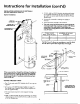
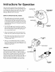
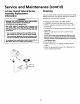
INSTALLATION SHOWING USE OF (OPTIONAL)
DELUXE HORIZONTAL VENT KIT:
3. 3" PVC, ABS, or CPVC Schedule 40 piping and fittings
Typical installation, are acceptable materials for the inlet vent system and for
the outlet vent system (after the first five feet for 75 Gal.
Models only).
AIRINTAKE 4. It cannot be connected to existing vent piping or
VENT TO _ chimney.
OUTDOORS 5. It must terminate vertically to the outdoors.
INTAKEFOR 6. The total vertical and horizontal run cannot exceedthe
COMBUSTIONAIR maximum length with a maximum number of 90"elbows
as specified in the table below. If more elbows are
FLUEPRODUCTS required, the venting distance must be reduced 5 feet for
DISCHARGE PIPE every 90° elbow.
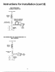
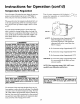
3" DIA. VENTS NUMBER OF 90"DEG.
MAX. LENGTH (FT.) ELBOWS*
45 1
40 2
35 3
*NOTE: Two 45" elbows are equivalent to one 90" elbow.
One 90* elbow equals 5 feet of equivalent vent length.
LAr_tal.$
If this concentric flue, through the wall type of venting sys- E_'T_(S_
tern is preferred, the vent kit can be ordered from Maytag
Customer Service at 1-800-788-8899 under kit #9002749.
See also page 40 and 41. Installation instructions are pro-
vided with the kit. _ [NTAI_
CL_g_CE
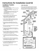
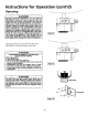
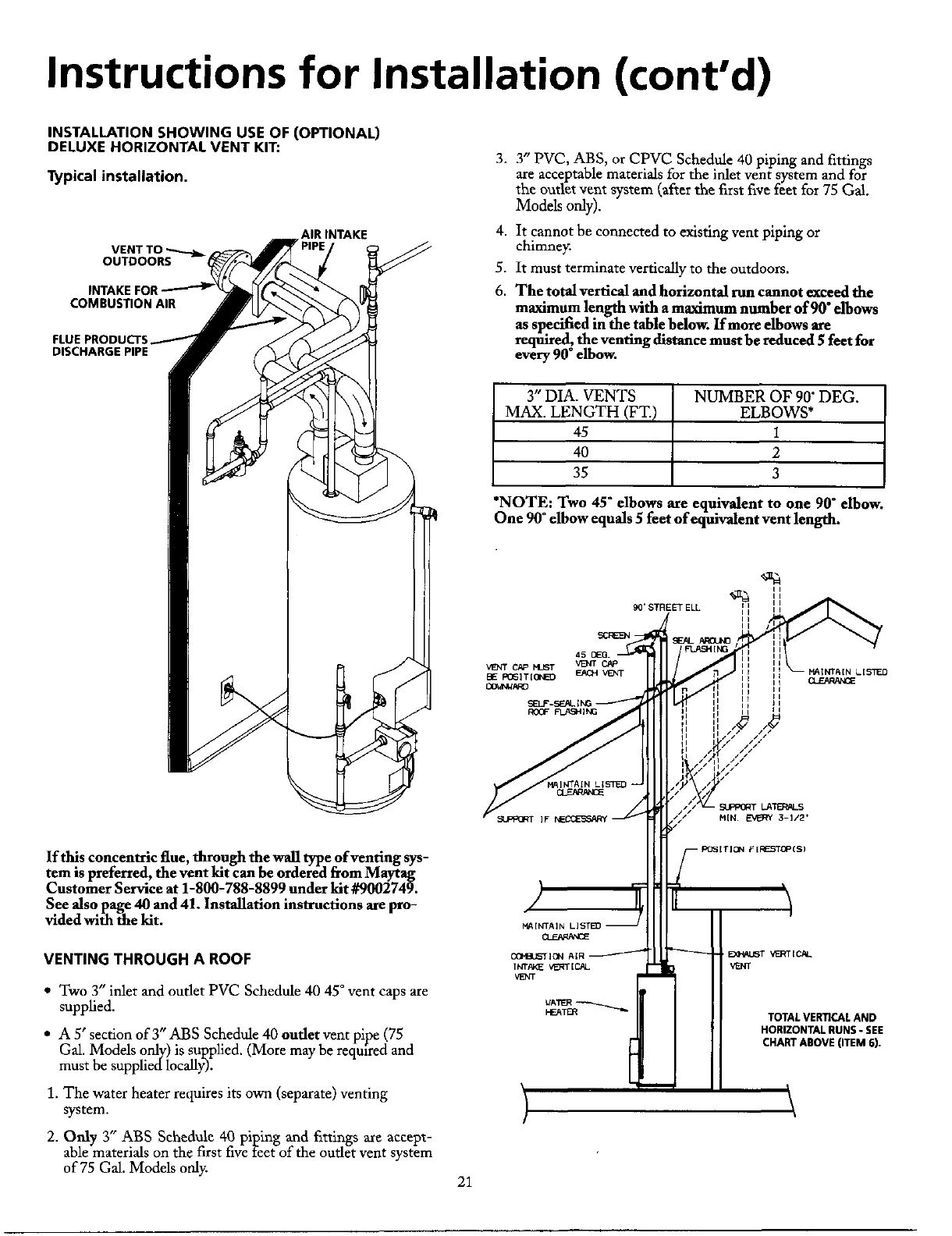
VENTING THROUGH A ROOF 0_ AIR _ VEI_FF[CJ&L
1NTP/._ vi_l" [C._L VENT
VENT
• Two 3" iulet and outlet PVC Schedule 40 45*vent caps are
supplied. _Aw
HE_--ER---_ TOTAL VERTICAL AND
• A 5' section ofY' ABS Schedule 40 outlet vent pipe (75 HORIZONTALNUNS- SEE
Gal. Models only) is supplied. (More may be reqm_redand CHARTABOVE(ITEM6).
must be supplied Iocally).
1. The water heater requires its own (separate) venting
system.
2. Only 3" ABS Schedule 40 piping and fittings are accept-
able materials on the first five feet of the outlet vent system
of 75 Gal. Models only.
21