Series Six POWER VENT GAS WATER HEATER USER’S GUIDE CANADIAN MANUAL FOR POTABLE WATER HEATING ONLY NOT SUITABLE FOR SPACE HEATING NOT FOR USE IN MANUFACTURED (MOBILE) HOMES Model Numbers • • • • • • Safety Instructions Installation Operation Care and Maintenance Troubleshooting Parts List HV640YBVITCGA HV650YBVITCGA HV640HBVITCGA HV650HBVITCGA C3 Technology® Gas Water Heaters meet the new ANSI Z21.10.
SAFE INSTALLATION, USE AND SERVICE Your safety and the safety of others is extremely important in the installation, use and servicing of this water heater. Many safety-related messages and instructions have been provided in this manual and on your own water heater to warn you and others of a potential injury hazard. Read and obey all safety messages and instructions throughout this manual.
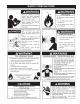
SAFETY PRECAUTIONS 3
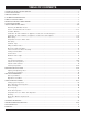
TABLE OF CONTENTS SAFE INSTALLATION, USE AND SERVICE .................................................................................................................................... 2 SAFETY PRECAUTIONS ................................................................................................................................................................. 3 TABLE OF CONTENTS ...........................................................................................................................
CUSTOMER RESPONSIBILITIES Thank You for purchasing a Maytag water heater. Properly installed and maintained, it should give you years of trouble free service. It is strongly suggested that this new water heater be professionally installed, contact Maytag Customer Service (1-800-788-8899) for recommended installers. of the water heater and your safety. Since we cannot put everything on the first few pages, READ THE ENTIRE MANUAL BEFORE ATTEMPTING TO INSTALL OR OPERATE THE WATER HEATER. 2.
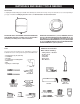
MATERIALS AND BASIC TOOLS NEEDED Accessories To simplify the installation Maytag has available the installation parts shown below. You may or may not need all of these accessories depending on your type of installation. Call Maytag Customer Service at 1-800-788-8899 for an authorized installer. EXPANSION TANKS FOR THERMAL EXPANSION CONDITIONS AVAILABLE IN 2 GALLONS (7.6 LITERS), Part No. 66001013 AND 5 GALLONS (18.9 LITERS), Part No. 66001014 CAPACITY.
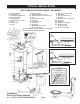
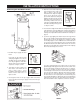
TYPICAL INSTALLATION GET TO KNOW YOUR WATER HEATER - GAS MODELS A B C D E F G H J Vent Pipe–Exhaust Vent Terminal Vent Adapter-Rubber Boot Blower Assembly Cold Water Inlet Inlet Water Shut-off Valve Union Inlet Dip Tube Anode** K L M N O P Q R S T U Hot Water Outlet Outlet Receptacle (115 VAC) Temperature-Pressure Relief Valve Flue Flue Baffle Assembly** Insulation Control Harness Rating Plate Gas Supply Manual Gas Shut-off Valve Ground Joint Union V W X Y Z AA BB CC DD EE Drip Leg (Sediment Trap) Drai
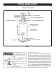
TYPICAL INSTALLATION MIXING VALVE USAGE FIGURE 2. HOTTER WATER CAN SCALD: Water heaters are intended to produce hot water. Water heated to a temperature which will satisfy space heating, clothes washing, dish washing, and other sanitizing needs can scald and permanently injure you upon contact. Some people are more likely to be permanently injured by hot water than others. These include the elderly, children, the infirm, or physically/mentally handicapped.
INSTALLATION INSTRUCTIONS Removing the Old Water Heater 4. Attach a hose to the water heater drain valve and put the other end in a floor drain or outdoors. Open the water heater drain valve. Open a nearby hot water faucet which will relieve pressure in the water heater and speed draining. The water passing out of the drain valve may be extremely hot. To avoid being scalded, make sure all connections are tight and that the water flow is directed away from any person, see Figures 3 and 6. FIGURE 6. 5.
INSTALLATIONS IN AREAS WHERE FLAMMABLE LIQUIDS (VAPORS) ARE LIKELY TO BE PRESENT OR STORED (GARAGES, STORAGE AND UTILITY AREAS, ETC.): Flammable liquids (such as gasoline, solvents, propane (LP or butane, etc.) and other substances (such as adhesives, etc.) emit flammable vapors which can be ignited by a gas water heater’s hot surface igniter or main burner. The resulting flashback and fire can cause death or serious burns to anyone in the area.
and 12" (30.5 cm) from the top. (Standard clearance.) If clearances stated on the heater differ from standard clearances, install water heater according to clearances stated on the heater. flammable in many cases, will also react to form corrosive hydrochloric acid when exposed to the combustion products of the water heater. The results can be hazardous, and also cause product failure.
2. When communicating with the outdoors through vertical ducts, each opening shall have a minimum free area of 1 square inch per 4,000 Btu per hour (5.5 cm2/kW) of total input rating of all equipment in the enclosure, see Figure 14. Chemical vapor corrosion of the flue, blower assembly and vent system may occur if air for combustion contains certain chemical vapors.
The water within the water heater tank expands as it is heated and increases the pressure of the water system. If the relieving point of the water heater’s temperature-pressure relief valve is reached, the valve will relieve the excess pressure. The temperature-pressure relief valve is not intended for the constant relief of thermal expansion. This is an unacceptable condition and must be corrected.
Figure 16 shows the typical attachment of the water piping to the water heater. The water heater is equipped with 3/4 inch NPT water connections. The valve must be marked with a maximum set pressure not to exceed the marked hydrostatic working pressure of the water heater (150 psi = 1,035 kPa) and a discharge capacity not less than the water heater input rate as shown on the model rating plate.
GAS PIPING When installed at elevations above 7,700 feet (2,347 m), input rating should be reduced at the rate of 4 percent for each 1,000 feet (305 m) above sea level which requires replacement of the burner orifice in accordance with Natural Gas and Propane Installation Code CAN/CSA B149.1. Contact your local gas supplier for further information.
Never use this water heater unless it is completely full of water. To prevent damage to the tank, the tank must be filled with water. Water must flow from the hot water faucet before turning “ON” gas to the water heater. SEDIMENT TRAPS To fill the water heater with water: 1. Close the water heater drain valve by turning the handle to the right (clockwise). The drain valve is on the lower front of the water heater. 2. Open the cold water supply valve to the water heater.
VENT CONNECTIONS TO BLOWER ASSEMBLY VENTING AND INSTALLATION Figure 15 shows the optimal placement of the 2" to 3" or 3" to 4" reducer; however, the vent can be reduced at any point in the vent system as long as the maximum vent length is not exceeded. Plan the layout of the vent system from the vent termination to the water heater considering all of the 90° and 45° elbows plus the number of feet of pipe that would be needed to install the total vent system.
CONDENSATION The unit may be vented horizontally through a wall or vertically through the roof. Pipe runs must be adequately supported along both vertical and horizontal runs as follows: Condensate formation does not occur in all installations of power vented water heaters, but should be protected against on installations where it can form in the venting system.
VENTING Vent pipes serving power vented appliances are classified by building codes as “vent connectors”. Required clearances from combustible materials must be provided in accordance with information in this manual under FACTS TO CONSIDER ABOUT THE LOCATION and VENT TERMINAL INSTALLATIONS, and with the Natural Gas and Propane Installation Code CAN/CSA B149.1 and local codes. VENT TERMINAL INSTALLATION 1.
FIGURE 23. This unit can vent through 2", 3" or 4" nonmetallic pipe and fittings. VERTICAL VENT RESTRICTIONS The vent pipe installation can be started from either the blower discharge or the termination wall. Keep in mind the total vent system (pipe and elbows) when installing the vent system, see VENTING AND INSTALLATION AND MAXIMUM VENT LENGTHS, pages 17 - 18. 1. Minimum of twelve 12" (30.5 cm) above the roof or twelve 12" (30.5 cm) above the anticipated snow level.
formamide (DMF) may be included to act as a retarding agent to extend curing time. Select the proper cement; Schedule 40 cement should be used for Schedule 40 pipe. Never use all-purpose cements, commercial glues and adhesives or ABS cement to join PVC or CPVC pipe and fittings. VENT PIPE PREPARATION 1. INITIAL PREPARATION A. Make sure the solvent cement you are planning to use is designed for the specific application you are attempting. B.
B. Deburring Use a knife, plastic pipe deburring tool, or file to remove burrs from the end of small diameter pipe. Be sure to remove all burrs from around the inside as well as the outside of the pipe. A slight chamfer (bevel) of about 10°15° should be added to the end to permit easier insertion of the pipe into the end of the fitting. Failure to chamfer the edge of the pipe may remove cement from the fitting socket, causing the joint to leak. STEP E F.
OPERATING INSTRUCTIONS FOR YOUR SAFETY READ BEFORE OPERATING WARNING: If you do not follow these instructions exactly, a fire or explosion may result causing property damage, personal injury or loss of life. BEFORE OPERATING: ENTIRE SYSTEM MUST BE FILLED WITH WATER AND AIR PURGED FROM ALL LINES. A. This appliance does not have a pilot. It is equipped with an ignition device which automatically lights the burner. Do NOT try to light the burner by hand. B.
To avoid any unintentional changes in water temperature settings, the control has a tamper resistant feature for changing the temperature setting. To change the temperature setting follow these instructions: TEMPERATURE REGULATION 1. “Wake Up” the temperature indicators by holding down both “COOLER” and “HOTTER” temperature adjustment buttons at the same time for one second, see Figure 26. One or two of the temperature indicators will light up.
FOR YOUR INFORMATION STRANGE SOUNDS Possible noises due to expansion and contraction of some metal parts during periods of heat-up and cool-down do not necessarily represent harmful or dangerous conditions. START UP CONDITIONS CONDENSATE Whenever the water heater is filled with cold water, some condensate will form while the burner is on. A water heater may appear to be leaking when in fact the water is condensate.
SERVICE AND ADJUSTMENT Soot build-up indicates a problem that requires correction before further use. Turn “OFF” gas to water heater and leave off until repairs are made, because failure to correct the cause of the sooting can result in a fire causing death, serious injury, or property damage. VENTING SYSTEM INSPECTION FIGURE 28. BURNER CLEANING In the event your burner or burner air openings require cleaning, turn the blower switch to the “OFF” position and allow the burner to cool.
ANODE ROD INSPECTION DRAINING The anode rod is used to protect the tank from corrosion. Most hot water tanks are equipped with an anode rod. The submerged rod sacrifices itself to protect the tank. Instead of corroding the tank, water ions attack and eat away the anode rod. This does not affect the water’s taste or color. The rod must be maintained to keep the tank in operating condition. The water heater should be drained if being shut down during freezing temperatures.
LEAKAGE CHECKPOINTS Use this guide to check a “Leaking” water heater. Many suspected “Leakers” are not leaking tanks. Often the source of the water can be found and corrected. Read this manual first. Then before checking the water heater make sure the gas supply has been turned “OFF”, and never turn the gas “ON” before the tank is completely full of water.
TROUBLESHOOTING GUIDELINES These guidelines should be used by a qualified Maytag Customer Service Center Agent. Call the Maytag Customer Service Center at 1-800-788-8899 for assistance. Inform the associate that this is a “Flammable Vapor Ignition Resistant” Product. PROBLEM LED STATUS SOLUTION A B C An open earth ground circuit to the ignition system. 1. Check that the earth ground connection is properly connected. 2. Check that the ground conductor on the water heater is properly connected.
TROUBLESHOOTING GUIDELINES These guidelines should be used by a qualified Maytag Customer Service Center Agent. Call the Maytag Customer Service Center at 1-800-788-8899 for assistance. Inform the associate that this is a “Flammable Vapor Ignition Resistant” Product.
REPAIR PARTS LIST MAYTAG GAS WATER HEATER HV640YBVITCGA HV650YBVITCGA HV640HBVITCGA HV650HBVITCGA MODEL NO’S 40 Gallon Natural Gas 50 Gallon Natural Gas 40 Gallon Propane (L.P.) 50 Gallon Propane (L.P.) BURNER ASSEMBLY OUTER DOOR (ALTERNATE) 1 16 Key No.
WARRANTY FULL ONE YEAR WARRANTY For one year from the date of original retail purchase, any part which fails in normal home use will be repaired or replaced free of charge. If a leak occurs in the tank, a new water heater of the closest capacity and quality then available, will be replaced free of charge. The warranty of the replacement is the balance of the original water heater’s warranty.