Service This manual is to be used by qualified appliance technicians only. Maytag does not assume any responsibility for property damage or personal injury for improper service procedures done by an unqualified person.
Important Information Important Notices for Servicers and Consumers Maytag will not be responsible for personal injury or property damage from improper service procedures. Pride and workmanship go into every product to provide our customers with quality products. It is possible, however, that during its lifetime a product may require service.
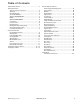
Table of Contents Important Information .................................................. 2 Safety Information Safety Practices for Servicer .................................. 5 Servicing ................................................................ 5 Receiving Range .................................................... 5 ALL APPLIANCES ................................................. 5 SELF-CLEANING OVEN ........................................ 5 OVEN ...................................................
Safety Information As with all appliances, there are certain rules to follow for safe operation. Verify everyone who operates the range is familiar with the operations and with these precautions. Use appliance only for its intended purpose as described. Pay close attention to the safety sections of this manual. Recognize the safety section by looking for the symbol or the word safety. ! To reduce the risk of the appliance tipping, it must be secured by a properly installed anti-tip bracket(s).
Safety Information Safety Practices for Servicer Safe and satisfactory operation of gas ranges depends upon its design and proper installation. However, there is one more area of safety to be considered: Servicing Listed below are some general precautions and safety practices which should be followed in order to protect the service technician and consumer during service and after service has been completed. 1. Gas smell—Extinguish any and all open flames and open windows. 2.
Safety Information OVEN In Case of Fire 1. Use Care When Opening Door—Let hot air or steam escape before removing or replacing food. Fires can occur as a result of over cooking or excessive grease. Though a fire is unlikely, if one occurs, proceed as follows: 2. Do Not Heat Unopened Food Containers—Build-up of pressure may cause container to burst and result in injury. 3. Keep Oven Vents Ducts Unobstructed. 4. Placement of Oven Racks—Always place oven racks in desired location while oven is cool.
Safety Information • Only certain types of glass/ceramic, earthenware, or other glazed utensils are suitable for oven use. Unsuitable utensils may break due to sudden temperature change. • Use care when opening oven door. Let hot air or steam escape before removing or replacing food. • Do not heat unopened food containers in oven. Build-up of pressure may cause a container to burst and result in injury. • Keep range vent ducts unobstructed. • Place oven racks in desired location while oven is cool.
Safety Information Product Safety Devices Safety devices and features have been engineered into the product to protect consumer and servicer. Safety devices must never be removed, bypassed, or altered in such a manner as to defeat the purpose for which they were intended. Listed below are various safety devices together with the reason each device is incorporated in the gas ranges. Pressure Regulator Maintains proper and steady gas pressure for operation of oven controls.
General Information This manual provides basic instructions and suggestions for handling, installing , and servicing electric ranges. The directions, information, and warnings in this manual are developed from experience with, and careful testing of the product. If the unit is installed according to the Installation Instructions, it will operate properly and will require minimal servicing. A unit in proper operating order ensures the consumer all the benefits provided by efficient electric cooking.
General Information Rating Label Model numbers are recorded on the rating label. Rating label is located on the rear left side of the interrior top burner box (remove the top burner grates and bowls), or on the right side of the burner box on some six burner models. Before ordering parts, write down the correct model and serial number from rating label. This avoids incorrect shipments and delays. Please refer to parts reference material when ordering replacement parts.
General Information Specifications Parts and Accessories Refer to individual Technial Sheet for information regarding specifications. Purchase replacement parts and accessories over the phone. To order accessories for your product call: Model Identification Complete registration card and promptly return. If registration card is missing: • For Amana product call 1-800-843-0304 or visit the Web Site at www.amana.com • For Maytag product call 1-800-688-9900 or visit the Web Site at www.maytag.
Troubleshooting Procedures ! WARNING To avoid risk of electrical shock, personal injury or death; disconnect power to oven before servicing, unless testing requires it. Problem Burners will not ignite; no spark at top burner. Possible Cause Poor ground on burner cap ......................... Weak or failed spark module....................... Low gas pressure ........................................ No 120 VAC to range .................................. Micro switch contacts not closing ................
Troubleshooting Procedures ! WARNING To avoid risk of electrical shock, personal injury or death; disconnect power to oven before servicing, unless testing requires it. Problem Possible Cause Open bake element ..................................... No bake element operation Loose wire connection or broken wire......... Open broil element ...................................... No broil element operation Loose wire connection or broken wire......... Power outage .......................................
Testing Procedures ! WARNING To avoid risk of electrical shock, personal injury or death; disconnect power to oven before servicing, unless testing requires power. Illustration Component Oven light socket Light switch Test Procedure Test continuity of receptacle terminals. Results Indicates continuity with bulb screwed in. Measure voltage at oven light. 120 VAC, see wiring diagram for terminal identification. If no voltage is present at oven light check wiring.
Testing Procedures ! WARNING To avoid risk of electrical shock, personal injury or death; disconnect power to oven before servicing, unless testing requires power. Illustration Component Limiter Pressure regulator Spark module Test Procedure Normally Closed Verify proper operation. Open .............320°F ......................... Manual Reset- Closed ...................... Verify gas pressure (WCP). If on LP service, verify proper gas supply conversion. Test for voltage at terminals L and N.........
Disassembly Procedures ! To avoid risk of electrical shock, personal injury or death; disconnect power to unit before servicing. WARNING Removing and Replacing Unit 1. Turn off power to the oven at the circuit breaker. NOTE: To avoid property damage, place a protective covering on the floor. 2. Slide unit forward, out of the installation position. 3. Disconnect or unplug the power cord leading from unit to junction box or outlet depending on connection. 4.
Disassembly Procedures ! To avoid risk of electrical shock, personal injury or death; disconnect power to unit before servicing. WARNING Terminal Block Single Feed Burner Gas Valve 1. Disconnect power supply to unit. 2. Remove control panel, see “Control Panel” procedure. 3. Remove screws securing static handle located under the static handle and above the lower heat shield. 4. Remove screws securing lower heat shield on the top side of the heat shield. 5.
Disassembly Procedures ! To avoid risk of electrical shock, personal injury or death; disconnect power to unit before servicing. WARNING Oven Thermostat Light Socket 1. 2. 3. 4. 1. 2. 3. 4. 5. Disconnect power and shut off gas supply to unit. Remove control panel, see “Control Panel” procedure. Remove maintop, see “Maintop” procedure. Remove screws securing sensing bulb to bracket, located inside the oven cavity. 5. Gently pull sensing bulb out through the oven cavity.
Disassembly Procedures ! To avoid risk of electrical shock, personal injury or death; disconnect power to unit before servicing. WARNING Convection Fan / Capacitor Bake Element 1. Disconnect power supply to unit. 2. Remove oven door, see “Oven Door” procedure. 3. Remove bake element, see “Bake Element” procedure. 4. Remove screws securing convection baffle to rear of oven cavity. 5. Remove screws securing convection fan to rear of oven cavity. 1. Disconnect power supply to unit. 2.
Disassembly Procedures ! To avoid risk of electrical shock, personal injury or death; disconnect power to unit before servicing. WARNING Door Gasket Door Hinge 1. Remove door gasket, by gently pulling the ends of the gasket out of the oven bottom front. 2. Release clips by squeezing metal clip together to remove out of the oven front frame. 1. Remove oven door, see “Oven Door” procedure. 2. Remove all torx screws securing top of door skin. 3.
Appendix A ©2004 Maytag Services 16022880 Rev.
Installation Instructions INSTALLATION MANUAL Professional 30”and 36” Dual Fuel Range Models 400 WEST FOURTH STREET, NORTH • NEWTON, IA 50208 Retain this manual for future reference. 17665 REV. C A–2 16022880 Rev.
Installation Instructions A MESSAGE TO OUR CUSTOMERS For your convenience, product questions can be answered by Jenn-Air Customer Assistance 1-800-JENNAIR (1-800-536-6247) 1-800-688-2080 (U.S. TTY for hearing or speech impaired) Mon. - Fri., 8 am - 8 pm Eastern Time Internet: www.jennair.com Maytag Services sm Attn: CAIRR Center P.O.
Installation Instructions TABLE OF CONTENTS INTRODUCTION ..................................................................................................................................................................3 MODEL IDENTIFICATION .............................................................................................................................................4 UNPACKING AND HANDLING .......................................................................................................
Installation Instructions INTRODUCTION Jenn-Air Professional Ranges are designed with a number of unique features certain to provide years of cooking enjoyment for the novice or experienced chef. Ranges are available in 30” and 36” widths. The large capacity electric ovens of the Dual Fuel Range are self-cleaning and feature convection baking. All models offer a minimum of (4) 15,000 Btu/hr sealed top burners. Dual-flow simmer burners are provided, and offer a low turn down of 570-1,200 Btu/hr.
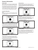
Installation Instructions MODEL IDENTIFICATION 36” DUAL FUEL RANGE MODEL MODEL PRD3630 30” DUAL FUEL RANGE MODEL OVEN ON HEATING HEATING DOOR LOCKED MODEL PRD3030 4 A–6 16022880 Rev.
Installation Instructions UNPACKING AND HANDLING MOVING AND PLACING THE RANGE The ranges have shipping weights varying from 420 lbs. to 630 lbs. less approx. 50 lbs. after removal of packing material. It is recommended that the door, grates, and front kick panel be removed to facilitate handling. This will reduce the weight for ease of handling. Kick Panel Fig. 2 CAUTION: Proper equipment and adequate manpower must be used in moving the range to avoid damage to the unit or the floor.
Installation Instructions UNPACKING AND HANDLING Remove the kick panel by removing two screws at the top and pulling forward. The range is held to the skid by two bolts in the front behind the kick panel, (fig. 3) and two L-brackets located on the bottom flange of the range back (fig. 3). After removing the bolts and brackets, the range must be lifted and removed from the skid. Due to the weight, a dolly with soft wheels should be used to move this unit.
Installation Instructions VENTILATION REQUIREMENTS A suitable exhaust hood must be installed above the range. The following chart indicates the minimum blower capacity recommended for hood ventilation.
Installation Instructions INSTALLING ANTI-TIP DEVICE All ranges must have an anti-tip device correctly installed as per the following instructions. If you pull the range out from the wall for any reason, make sure that the device is properly engaged when you push the range back against the wall. If it is not, there is a possible risk of the range tipping over and causing injury if you or a child stand, sit or lean on an open oven door.
Installation Instructions CABINET PREPARATION 1) The range is a free standing unit. If the unit is to be placed adjacent to cabinets, the clearances shown in fig. 9 (PRD3630) & fig. 10 (PRD3030) are required. The same clearances apply to island installations. 2) The range can be placed in various positions with respect to the cabinet front, with the front either flush or projecting, depending on the countertop depth. 3) The gas and electrical supply should be within the zones shown (fig. 9, 10 & 11).
Installation Instructions CABINET PREPARATION min. 30" wide hood 13" 12" min. to combustible material , each side 18" Min. 7" 9" Max 10-3/4" 2" CAUTION: 36" min. to combustible material , from cooking surface cooking surface 4" 1-1/2" electrical gas supply supply 35-3/4" max. for level counter, 37" max. with range leveling legs fully extended ∆ As defined in the “National Fuel Gas Code” (ANSI Z223.1, lastest edition).
Installation Instructions CABINET PREPARATION STANDARD INSTALLATION: ISLAND INSTALLATION: 12" Min. to Combustibles without backguard G High Shelf Backguard H A Low Backguard B C (Dim. “B”) D 36" Min. to Combustibles Island Trim (Dim.“A”) 0” Clearance 0” Clearance E F J I As defined in the “National Fuel Gas Code” (ANSI Z223.1, Latest Edition). The horizontal surfaces of the range top (cooktop) trim must not be below countertop level. Fig.
Installation Instructions BACKGUARD INSTALLATION BACKGUARD KITS: Model PRD3030 is shipped standard with a 9”Low backguard. High Shelf backguards, Island Trims and the Low Back for Model PRD3630 must be ordered separately. Specific instructions for installation of the High Shelf backguard, Low backguard or Island Trim Backguard can be found packaged with the backguard. All backguards or island trims must be installed on the range before the unit is pushed into the cabinet.
Installation Instructions ELECTRICAL / GAS CONNECTIONS RECOMMENDED GROUNDING METHOD This appliance is factory equipped with a power supply cord with a four-prong grounding plug. It must be plugged into a mating grounding, type receptacle, connected to a correctly polarized 120/240 volt circuit.
Installation Instructions HOOK-UP TO GAS SUPPLY CAUTION: The appliance must be isolated from the building’s gas supply piping system by closing its individual manual shut-off valve during any pressure testing of the gas supply piping system at test pressures equal to or less than 1/2 psig (3.5kPa.). The appliance and its individual shut-off valve must be disconnected from the gas supply piping system during any pressure testing of the system at the test pressures in excess of 1/2 psig (3.5kPa.).
Installation Instructions INSTALLER FINAL CHECKLIST GENERAL Placement of unit. Specified clearance maintained to cabinet surfaces. Unit Level - front to back, side to side. All packaging material and tie straps removed, drip pans clean and empty. Backguard attached if there is less than 12" clearance above the cooking surface to combustibl construction behind unit. Island trim attached if there is more than 12” clearance above the cooking surface to the combustible construction behind the unit.
Installation Instructions WARRANTY FULL ONE YEAR WARRANTY - PARTS AND LABOR For one (1) year from the original retail purchase date, any part which fails in normal home use will be repaired or replaced free of charge.
Installation Instructions WARRANTY 6. Consequential or incidental damages sustained by any person as a result of any breach of these warranties. Some states do not allow the exclusion or limitation of consequential or incidental damages, so the above exclusion may not apply. IF YOU NEED SERVICE ■ Call the dealer from whom your appliance was purchased or call Maytag ServicesSM, Jenn-Air Customer Assistance at 1-800-JENNAIR (1-800-536-6247) to locate an authorized servicer.