
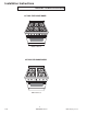
Specifications


A–8 16022880 Rev. 0 ©2004 Maytag Services
Installation Instructions
6
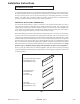
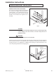
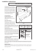
UNPACKING AND HANDLING
Remove the kick panel by removing two screws at
the top and pulling forward. The range is held to the
skid by two bolts in the front behind the kick panel,
(fig. 3) and two L-brackets located on the bottom
flange of the range back (fig. 3). After removing the
bolts and brackets, the range must be lifted and
removed from the skid.
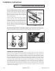
Due to the weight,a dolly with soft wheels should be
used to move this unit. The weight must be
supported, uniformly across the bottom (fig. 4). To
remove the door, open the door and hold it all the
way open. Close the hinge latches (fig. 5) and release
the door. The door can then be removed by gently
lifting and pulling the door, with the hinges up and
out of the frame (fig. 6).
The professional range should be transported by a dolly close to its final location. The range can be
tipped back and supported on the rear legs while the dolly is removed. The floor under the legs should
be protected (Wood Strips, Carpet, Paneling, etc.) before pushing the unit back into position.
22"
Leveling Legs
Range Must
be Uniformly
Supported
on Braces
Fig. 4
Range Must
be Uniformly
Supported on
Braces
Leveling Legs
MOVING AND PLACING THE RANGE
Electric and gas connections should be made before the range is slid into the cabinet opening (see
page 9 & 10). The backguard or island trim should also be installed before the range is placed in its
final position (refer to page 12). For proper performance, the professional range should be level. To
achieve a flush fit of the range to adjoining countertops, it will be necessary to have level cabinets
(front to back, and left to right across opening of the range). After checking the countertops for level
and before sliding the range into place, measure the distance from the floor to the top of the counter
work surface in the rear left and right corners. Adjust the corresponding rear corner of the range to an
equal height of the counter, as the rear leveling legs are not accessible once the range is pushed into
place. Once the range is in place, the front leg levelers can be accessed to level the front of the range.
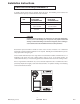
Replace the kick panel and oven door by reversing the procedure described previously. It is important
that the two screws retaining the kick panel are secure to prevent accidental access to live electrical
components and wires (fig. 2).
DOOR HINGE ROLLER
DOOR HINGE ROLLER
Fig. 5
Lock
(close)
Unlock
Fig. 6
Lock
(close)
Unlock
DOOR HINGE ROLLER-
LEFT
DOOR HINGE ROLLER-
RIGHT