This manual is to be used by qualified appliance technicians only. Maytag does not assume any responsibility for property damage or personal injury for improper service procedures done by an unqualified person.
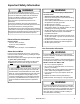
Important Information Important Notices for Servicers and Consumers Maytag will not be responsible for personal injury or property damage from improper service procedures. Pride and workmanship go into every product to provide our customers with quality products. It is possible, however, that during its lifetime a product may require service.
Table of Contents Important Information ...................................................... 2 Important Safety Information ........................................... 4 General Information Model Identification ..................................................... 8 Serial Label Location ................................................... 8 Model Nomenclature ................................................... 9 Model Specifications .................................................
Important Safety Information ! WARNING To avoid risk of fire, electric shock, serious injury, or death when using your dryer, follow these basic precautions: 1. Read all instructions before using dryer. 2. Install dryer according to Installation Instructions. Refer to the Grounding Instructions in the Installation Instructions for proper grounding of the dryer. 3.
Important Safety Information ! ! WARNING WARNING The California Safe Drinking Water and Toxic Enforcement Act of 1986 (Proposition 65) requires the Governor of California to publish a list of substances known to the State of California to cause cancer or reproductive harm and requires business to warn consumers of potential exposures to such substances.
Important Safety Information 6 16022785 Rev.
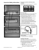
Important Safety Information For proper operation at altitudes above 2,500 feet The natural gas valve spud orifice size must be reduced to ensure complete combustion. See table. Altitude Ft (M) 3000 (915) 6000 (1830) 8000 (2440) 9000 (2740) 10000(3050) Orifice Size # 43 44 45 46 47 Part number 503778 58719 503779 503780 503781 Gas Connection Connect gas supply to dryer using a new stainless steel flexible connector or hard pipe (check local codes) according to illustration.
4. Retest connection for leak after tightening or adding joint compound. • Retest any connections that were disturbed. L.P./Propane DO NOT connect dryer to L.P./Propane gas service without converting the gas valve. A Sales Accessory L.P./ Propane Gas Conversion Kit 63-6766 must be installed. General Information Model Identification Complete registration card and promptly return. If registration card is missing: • For Maytag product call 1-800-688-9900 or visit the Web Site at www.maytag.
General Information Drying Center Nomenclature Drying Center Nomenclature M C E 8 0 0 0 A Y W Color W Q Brand A C G H J M N U Y Amana Magic Chief Graffer & Sattler Hardwick Jenn-Air Maytag Norge Universal Crosley White Bisque Listing W Y Z Y Product Type C Drying Center 120V-60hz 240V-60hz Canada 240V-60hz 220-240 V / 50-60 Hz Marketing Code Fuel G E This identifies which version of production the unit is.
General Information UPPER DRYING CABINET Capacity (cu. ft.) Controls Drying System C.F. M. 17.3 LED BreezeCare™ 80 MODEL MCE/G8000 R T R W Low Extra Low Flat Dry Shelves 140º F 110º F 5 W LOWER TUMBLE DRYER Controls Drying System C.F.M. Cycles Wrinkle Release LED GentleBreeze™ 170 4 • DRYING CENTER SPECIFICATIONS W T Uncrated Dimensions: 33 1 /2"w x 29"d x 74"h Regular Medium Low Extra Low 150º F 145º F 140º F 125º F Crated Dimensions: 36.8"w x 31.3"d x 76.3"h Uncrated Weight: 245 lbs.
Troubleshooting Procedures ! WARNING To avoid risk of electrical shock, personal injury or death, disconnect power to unit before servicing, unless testing requires power. Troubleshooting Guide Maytag Neptune™ Drying Center • Due to possibility of personal injury or property damage, always contact an authorized technician for servicing or repair of this unit. • Faulty Heater Relays.
Troubleshooting Procedures ! WARNING To avoid risk of electrical shock, personal injury or death, disconnect power to unit before servicing, unless testing requires power. • Clothes too wet due to insufficient spin out by washer. Note: Pressing the Off button exits the Diagnostic State • Faulty Sensor Bar. See Sensor Bar diagnostic section. and places the control board in the Sleep State.
Troubleshooting Procedures ! WARNING To avoid risk of electrical shock, personal injury or death, disconnect power to unit before servicing, unless testing requires power. Example: 1) To read measured temperature, scroll to “rd” on the menu and press Signal (+). 2) Upon entry to the utility, “OFF” appears on the display. 3) Using the Time Adjust v arrow button scroll to “Ld” menu item from the Table. Note: To exit the utility before running a test, press Signal (-). The display will show “rd”.
Troubleshooting Procedures ! WARNING To avoid risk of electrical shock, personal injury or death, disconnect power to unit before servicing, unless testing requires power.
Troubleshooting Procedures ! WARNING To avoid risk of electrical shock, personal injury or death, disconnect power to unit before servicing, unless testing requires power. 2) “HP” The thermistor reading is out of range and the db*****Sensor Bar Diagnostics dryer cycle is interrupted. Consumer may push the "Off" Key and attempt to run the cycle again.
Troubleshooting Procedures ! WARNING To avoid risk of electrical shock, personal injury or death, disconnect power to unit before servicing, unless testing requires power. Membrane Pad Continuity Checks Membrane shown with console tipped forward for service. Pin Number J1A 12 12 1 12 1 12 1 1 J2A J1B J2B Plug Number Manual Membrane Pad Check NOTE: Unplug connector and touch probe of meter to the appropriate pin numbers.
Troubleshooting Procedures ! WARNING To avoid risk of electrical shock, personal injury or death, disconnect power to unit before servicing, unless testing requires power.
Troubleshooting Procedures ! WARNING To avoid risk of electrical shock, personal injury or death, disconnect power to unit before servicing, unless testing requires power.
Disassembly Procedures ! To avoid risk of electrical shock, personal injury or death; disconnect power to unit before servicing. WARNING Lower Door Reversal/Removal 1. Disconnect power supply to unit. 2. Remove 4 door screws and 4 cover screws from side opposite hinges. 3. Remove hinges from door and cabinet and install them on desired side. 4. Install filler screws and covers. 5. Move door strike and catch to opposite side. Shaker Removal 1. Disconnect power supply to unit. 2.
Disassembly Procedures ! To avoid risk of electrical shock, personal injury or death; disconnect power to unit before servicing. WARNING 3. Unhook left and right side hanger from Shaker. 5. Slide Shaker Hangers through the top of the cabinet. The angled edge faces the front of the unit. Console Removal 1. Disconnect power supply to unit. 2. Remove the 4 screws located in the drying cabinet securing the console from behind, one on each side and two in the middle. 4.
Disassembly Procedures ! To avoid risk of electrical shock, personal injury or death; disconnect power to unit before servicing. WARNING 3. Roll console out and down. Logic Board Removal 1. Disconnect power supply to unit. 2. Remove Console. 3. Unlatch and disconnect the three plug-in connectors from logic control board, remove ground wire from the chassis and carefully remove the four flex circuit connectors. 4.
Disassembly Procedures ! To avoid risk of electrical shock, personal injury or death; disconnect power to unit before servicing. WARNING 4. Remove Spacer Support. 5. Disconnect wires to door switch. 6. Disconnect harness to Sensor and lift Front Panel off tabs on left and right sides of Base Frame. 22 16022785 Rev.
Disassembly Procedures ! To avoid risk of electrical shock, personal injury or death; disconnect power to unit before servicing. WARNING Heater Assembly Removal Tumbler Drum Removal 1. 2. 3. 4. 5. Disconnect power supply to unit. Remove Console. Remove the Front Panel. Remove Belt From Idler Pulley. Remove top left screw attaching the Water Dipenser Housing. 1. 2. 3. 4. 5. 6. Disconnect power supply to unit. Remove Console. Remove the Front Panel. Remove Belt From Idler Pulley. Remove Tumbler Drum.
Disassembly Procedures ! To avoid risk of electrical shock, personal injury or death; disconnect power to unit before servicing. WARNING Relay Board Removal 1. 2. 3. 4. Disconnect power supply to unit. Remove Console. Remove the Front Panel. Remove screw, lift front of board up and pull toward front of machine 8. Carefully work Blower Wheel off the Motor Shaft. Blower and Motor Removal 1. 2. 3. 4. 5. 6. Disconnect power supply to unit. Remove Console. Remove the Front Panel.
Disassembly Procedures ! To avoid risk of electrical shock, personal injury or death; disconnect power to unit before servicing. WARNING 11. Rotate motor counterclockwise approx. 45 degrees. Lift up on the back of the Motor and pull out of the Front Support. Steamer Blower Removal 1. 2. 3. 4. 5. 6. Disconnect power supply to unit. Remove Console. Remove the Front Panel. Remove Hose on back of Water Valve. Slide Water Valve Assembly toward front and remove.
Disassembly Procedures ! To avoid risk of electrical shock, personal injury or death; disconnect power to unit before servicing. WARNING Steamer Heater Removal 1. 2. 3. 4. 5. 6. Disconnect power supply to unit. Remove Console. Remove the Front Panel. Remove Hose on back of Water Valve. Slide Water Valve Assembly toward front and remove. Loosen screws securing Blower Assembly and remove. 7. Slide Heater Assembly out the front of unit. 26 16022785 Rev.
Appendix A ©2003 Maytag Appliances Company 16022785 Rev.
16022785 Rev.
©2003 Maytag Appliances Company 16022785 Rev.
16022785 Rev.
©2003 Maytag Appliances Company 16022785 Rev.
16022785 Rev.
©2003 Maytag Appliances Company 16022785 Rev.
16022785 Rev.
©2003 Maytag Appliances Company 16022785 Rev.
16022785 Rev.
©2003 Maytag Appliances Company 16022785 Rev.
16022785 Rev.
©2003 Maytag Appliances Company 16022785 Rev.
16022785 Rev.
Appendix B 40 16022785 Rev.
©2003 Maytag Appliances Company 16022785 Rev.
42 16022785 Rev.
©2003 Maytag Appliances Company 16022785 Rev.
44 16022785 Rev.
©2003 Maytag Appliances Company 16022785 Rev.
46 16022785 Rev.
©2003 Maytag Appliances Company 16022785 Rev.
48 16022785 Rev.
©2003 Maytag Appliances Company 16022785 Rev.
50 16022785 Rev.
©2003 Maytag Appliances Company 16022785 Rev.
52 16022785 Rev.
©2003 Maytag Appliances Company 16022785 Rev.
54 16022785 Rev.
©2003 Maytag Appliances Company 16022785 Rev.
56 16022785 Rev.
©2003 Maytag Appliances Company 16022785 Rev.