MLG-45PDB Installation Manual Stack Dryer RETAIN THESE INSTRUCTIONS IN A SAFE PLACE FOR FUTURE REFERENCE Part No.
Dryer Safety Your safety and the safety of others are very important. We have provided many important safety messages in this manual and on your appliance. Always read and obey all safety messages. This is the safety alert symbol. ! This symbol alerts you to potential hazards that can kill or hurt you and others. All safety messages will follow the safety alert symbol and either the word “DANGER” or “WARNING”.
WARNING: Gas leaks cannot always be detected by smell. Gas suppliers recommend that you use a gas detector approved by UL or CSA. For more information, contact your gas supplier. If a gas leak is detected, follow the “What to do if you smell gas” instructions. In the State of Massachusetts, the following installation instructions apply: ■ Installations and repairs must be performed by a qualified or licensed contractor, plumber, or gasfitter qualified or licensed by the State of Massachusetts.
Important Information ________________ IMPORTANT: A means of restraint must be used to prevent straining of the gas supply when the dryer is moved. An external means of power removal (disconnect device) must be provided by the installer. Table of Contents ________ SPECIFICATIONS ....................................................... 5 INSTALLATION PROCEDURES .................................. 6 Location Requirements ...........................................
Specifications _______________________________________________________________________ Gas MAXIMUM CAPACITY (DRY WEIGHT) PER POCKET TUMBLER DIAMETER TUMBLER DEPTH TUMBLER VOLUME PER POCKET TUMBLER/DRIVE MOTOR PER POCKET BLOWER/FAN MOTOR PER POCKET DOOR OPENING (DIAMETER) DOOR SILL HEIGHT TOP POCKET / BOTTOM POCKET DRYERS PER 20’/40’ CONTAINER DRYERS PER 48’/53’ TRUCK VOLTAGE AVAILABLE APPROXIMATE NET WEIGHT APPROXIMATE SHIPPING WEIGHT AIRFLOW PER POCKET 60 Hz 50 Hz HEAT INPUT PER POCKET EXHAUST CONNEC
Installation Procedures _______________ Location Requirements _______________ ! WARNING ▲ ! WARNING ▲ Excessive Weight Hazard Use two or more people and mechanical equipment to lift, move and install dryer. Failure to do so can result in back or other injury. Explosion Hazard Installation should be performed by competent professional in accordance with local, state, and country codes. In the absence of these codes, the installation must conform to applicable American National Standards: ANSI Z223.
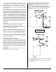
Dryer Enclosure Requirements _______ A = 20-inches (50.80 cm) B = 22.5-inches (57.15 cm) A The requirement to allow the dryer door to open completely is 33.5-inches (85.1 cm). B A minimum overhead clearance of 12-inches (30.48 cm) is required. C Dryer should be positioned a minimum of 12-inches (30.48 cm) away from the nearest obstruction. 24-inches (60.96 cm) is recommended for ease of installation, maintenance, and service. D 1/16” (1.5875 mm) minimum is required.
As per the National Fuel Gas Code, “Exhaust ducts for type 2 clothes dryers shall be constructed of sheet metal or other noncombustible material. Such ducts shall be equivalent in strength and corrosion resistance to ducts made of galvanized sheet steel not less than 26 gauge (0.0195-inches [0.50 mm]) thick.” The ductwork should be laid out in such a way that the ductwork travels as directly as possible to the outdoors with as few turns as possible. Single or independent dryer venting is recommended.
Single Dryer Venting without Transition Piece The illustration below shows the minimum cross-sectional area for multiple dryer round or square venting. These figures must be increased if the main duct run from the last dryer to where it exhausts to the outdoors is longer than 20 feet (6.09 meters) or has more than 1 elbow in it. Multiple Dryer Venting with 10-Inch (25.4 cm) Diameter 1,200 cfm (33.
Electrical Information _________________ Grounding Electrical Requirements A ground (earth) connection must be provided and installed in accordance with local, state, and national regulations or codes of the country of destination. In the absence of these codes, grounding must conform to applicable requirements of the National Electrical Code ANSI/NFPA NO. 70-LATEST EDITION, or in Canada, the installation must conform to applicable Canada Standards: Canadian Electrical Codes Parts 1 & 2 CSA C22.
Insert the wiring from the two 120 volt 15 amp circuits (one for top tumbler and one for bottom tumbler) into the strain reliefs. Gas Information _______________________ Determine the top pocket electrical connections by checking wire label, which will be marked “top”. ! WARNING ▲ Connect wiring from 120 volt 15 amp circuit to top pocket wiring as described in the following illustration (black to black, white to white and green to chassis ground wire).
The input ratings shown on the data label are for elevations up to 2,000 feet (610 meters), unless elevation requirements of over 2,000 feet (610 meters) were specified at the time the dryer order was placed with the factory. The adjustment or conversion of dryers in the field for elevations over 2,000 feet (610 meters) is made by changing each burner orifice. If this conversion is necessary, contact the distributor who sold the dryer or contact the manufacturer.
Preoperational Test ___________________ Shutdown Instructions ________________ All dryers are thoroughly tested and inspected before leaving the factory. However, a preoperational test should be performed before the dryer is publicly used. It is possible that adjustments have changed in transit or due to marginal location (installation) conditions. If the dryer is to be shutdown (taken out of service) for a period of time, the following must be performed: Turn on electric power to the dryer.
Suggested Cleaning Schedule ! WARNING ▲ Electrical Shock Hazard Disconnect power before servicing. Replace all parts and panels before operating. Failure to do so can result in death or electrical shock. Adjustments 7 Days After Installation and Every 12 Months Thereafter Inspect bolts, nuts, screws, setscrews, grounding connections and nonpermanent gas connections (unions, shutoff valves, and orifices). Belts should be examined. Cracked or seriously frayed belts should be replaced.