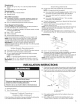
BUILT-IN DISHWASHER INSTALLATION INSTRUCTIONS INSTRUCTIONS D'INSTALLATION DU LAVEP VAISSELLE ENCASTRE Table of Contents/Table des matieres ............................................................................. IM PORTANT: Save for local electrical inspector's use. Installer: Leave installation instructions with the homeowner. Homeowner: Keep installation instructions IMPORTANT : Conserver pour consultation Installateur Propri_taire par I'inspecteur for future reference.
TABLEOF CONTENTS DISHWASHER SAFETY ............................................................................... INSTALLATION REQUIREMENTS ............................................................. Tools and Parts ......................................................................................... 2 Prepare Dishwasher ................................................................................. 3 3 Make Electrical Connections--Power Location Requirements ................................
Tip Over Hazard Do not use dishwasher until completely installed. Do not push down on open door. Doing so can result in serious injury or cuts. You need to: • Install this dishwasher as specified in these instructions. • • • Have everything you need to properly install dishwasher. Contact a qualified installer to ensure that dishwasher is installed to meet all electrical and plumbing national and local codes and ordinances.
Minimum Clearances Check location where the dishwasher will be installed. The location must provide: • Easy access to water, electricity and drain. • Convenient access for loading and unloading dishes. Corner locations require 2" (5.1 cm) minimum clearance between the side of the dishwasher door and the wall or cabinet. • A minimum of 255/8'' (65.1 cm) is required in front of the dishwasher to allow the door to open fully. Electrical Shock Hazard Plug into a grounded 3 prong outlet.
Requirements: • 120-volt, 60 Hz, AC-only, 15- or 20-amp fused electrical supply Use the new drain hose supplied with your dishwasher. NOTI:: If a longer drain hose is required: • Copper wire only, 2 wire with ground Recommended: • • Time-delay fuse or circuit breaker Separate circuit • Use a new drain hose with maximum length of 12 ft (3.7 m) that meets all current AHAM/IAPMO test standards. • Use a new drain hose that is resistant to heat and detergent. • Use a new drain hose that fits the 1" (2.
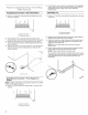
2. HOOHUpS Instal 1. Electrical Connection--Direct A Install Water Line Wire Method Drill a 3/4"(1.9 cm) hole in the right-hand cabinet side or the rear of the opening. If the cabinet is wood, sand hole until smooth. If the cabinet is metal, cover the hole with a grommet (Part Number 302797) included with power supply cord kit. See "Electrical Requirements." 1. B Drill a 1/2=(1.3 cm) hole in the left-hand cabinet side or the rear of opening. A B A. Preferred locations B.
5= Turn on the water shutoff valve. Run water into a shallow pan to flush the water line (copper tubing or flexible braided water supply line) of particles that may clog the inlet valve. 3= Use a rubber hose connector (not provided) with screw-type clamps (not provided) to connect the air gap to the waste disposer inlet above the drain trap and at least 20" (50.8 cm) above the floor. A B H G F 6. Turn off the water shutoff valve. A.
3. Usearubberhoseconnector (notprovided) withscrew-type clamps (notprovided) toconnect theairgaptothewastetee abovethedraintrapandatleast20"(50.8cm)abovethefloor. NOTE: It isrecommended thatthedrainhosebelooped up andsecurely fastened totheunderside ofthecounter. A A B B C E A. Large drain hose clamp (provided) B. Drain hose 3. A. Drain hose-- cut here, if needed B. Screw-type clamps (not provided) C. Air gap D. Large drain hose clamp (provided) 4. C. Disposer inlet D.
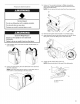
3. Using a 1/4"hex socket, nut driver or Phillips screwdriver, remove the 4 screws attaching the toekick panel and lower panel to the dishwasher. NOTE: Do not remove the tech sheet from the access panel. 4. 5. Remove both panels and set aside on a covered surface. Apply plumber's tape or pipe joint compound to the 90 ° elbow fitting and connect the fitting to the water inlet valve. 6. Tighten the 90 ° elbow fitting until snug. NOTE: Elbow should face to the rear of the dishwasher.
2. Prepare 1. Terminal Box Pull the power supply cord through the conduit connector in the terminal box. Using a 1/4"hex-head socket, nut driver or Phillips screwdriver, remove the terminal box cover. Lay the cover aside. 0 \ 3. 2= Install a UL-listed/CSA-approved conduit connector (may be provided in power supply cord kit [Part Number 4317824]). Check that screwheads are facing to the left when tightening the conduit nut.
5, Using UL-listed/CSA approved twist-on connectors sized to connect power supply cord to 16-gauge dishwasher wire, connect the black wire from the power supply cord to the black wire on the terminal box. 6, Tighten the conduit connector screws to secure the power supply cord. 1, Measure the cabinet opening height. 2, Adjust the dishwasher leg height according to the following chart. Turn both of the leveler legs to the same height.
2. Cut the sound barrier strips to align with the drawers and cabinet doors. 3= Reinstall the sound barrier strips by sliding the strips down onto the door sides. 4. Check that the sound barrier strips align with the top strip as shown. 5. Remove the top sound barrier strip by sliding the strip to the right. Cut the sound barrier strip to align with the drawers and cabinet doors. Using 2 or more people, stand dishwasher upright.
7, Reinstall the top sound barrier strip by sliding the strip onto the top of the dishwasher door. 5, 6. For power supply cord installations--route the power supply cord through the cutout in the cabinet. Move the dishwasher completely into the cabinet opening. NOTE: Do not kink or pinch the water line, drain hose, power supply cord or direct wire between the dishwasher and the cabinet. 7. Remove the cardboard from underneath the dishwasher.
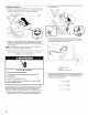
12. Repeat for the other side of the dishwasher. 13. Place the level against the top front opening of the tub. 14. Check that the dishwasher is level from side to side. If the dishwasher is not level, adjust the front legs up or down until the dishwasher is level. 7= Hold the 90 ° elbow fitting with one adjustable wrench and tighten the nut with the second adjustable wrench or 5/8"openended wrench. 8. Place paper towel under the elbow. 9. Turn on the water supply. 10. Check for leaks. We ....
3. 4. 5. Form a U-shaped hook on the bare ground wire. Wrap the ground wire hook clockwise around the green grounding screw and under the washer. Tighten the green grounding screw. 10. Using a 1/4"nut driver and previously removed screw, reinstall the terminal box cover with the wires inside terminal box. % C 11. Check that no wires are pinched by the cover. A. Bare ground wire B. Washer C.
2. 3. 4. Open the dishwasher door and remove the lower dish rack. Place a towel over the pump assembly and spray arm of the dishwasher to keep the screws from falling into the pump area during installation. 6. For wood underside counters only, use 1/8"drill bit to drill holes through the top mounting strip into the wood underside of the counter. 7. Use the countertop to the counter. 8. 9. Remove the towel from the dishwasher. Reinstall the lower dish rack.
5. On some models with sound seals, measure the distance from the bottom of the dishwasher to the floor. Trim the sound seals to the correct size. 6. Install the sound seals. 7. Installation is completed. 4. 1. On some models, remove the backing and attach the sound barrier strip below the dishwasher door. 2. Reinstall the lower panel first. 3. Reinstall the access panel.
Direct Wire Method Check Dishwasher Operation 1. Read the Dishwasher User Instructions dishwasher. 2. Check that all parts have been installed and no steps were skipped. Check that you have all the tools you used. Start the dishwasher and allow it to complete the shortest wash cycle. After 2 minutes, unlatch the door. Wait 5 seconds, and then open the door. Check that there is water in the bottom of the dishwasher tub. 3. 4. Electrical Electrically ground Connect ground terminal box. 5.
SECURITEDU LAVE-VAISSELLE Votre securite et celle des autres est tres importante. Nous donnons de nombreux messages de s_curit_ importants dans ce manuel et sur votre appareil m_nager. Assurez-vous toujours lire tous les messages de s_curit_ et de vous y conformer. de Ce symbole d'alerte de s_curit_ vous signale les dangers potentiels de d_c_s et de blessures graves & vous et & d'autres.
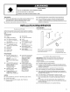
EXIGENCES D'INSTALLATION Pi_ces fournies Verifier la presence de toutes les pieces. Rassembler les outils et pieces n@cessaires avant de commencer I'installation. Lire et suivre les instructions fournies avec les outils indiqu6s ici. B j,/_ C o Outillage n_cessaire • Pince • Cale en bois • • • • • • • Tournevis Philips Tournevis & lame plate Douilles hexagonales/ tourne-ecrou--%d' et 1¼.
D_gagements minimums Inspecter I'emplacement d'installation du lave-vaisselle. II dolt comporter les caracteristiques suivantes : • Facilite d'acces aux canalisations d'eau et d'evacuation et &la source d'electricit& • • Acces facile pour chargement et dechargement de la vaisselle. Dans le cas de I'installation dans un angle, on dolt pouvoir etablir un degagement minimal de 2" (5,1 cm) entre le c6te de la porte du lave-vaisselle et le mur ou le placard.
Specifications : • Source d'alimentation de 120 V, 60 Hz, CA uniquement, de type 15 ou 20 amperes, protegee par fusible et reliee & la terre • Fil de cuivre uniquement, & 2 conducteurs Recommand_ • • : Fusible ou disjoncteur temporise Circuit distinct M_thode de raccordement direct • Utiliser des conducteurs de cuivre gaines non metalliques ou blindes souples avec conducteur de liaison & la terre qui satisfassent aux exigences de I'installation electrique de votre domicile, et qui soient conformes aux
INSTRUCTIONSD'INSTALLATION Raccordement _lectrique-direct Risque de choc _lectrique Interrompre I'alimentation _lectrique avant d'instailer le lave=vaisseiie (au niveau du tableau de distribution fusible ou disjoncteur) 1. Percer un trou de 3/4"(1,9 cm) dans la paroi de droite du placard, la paroi arriere ou le plancher de I'ouverture d'encastrement. = A Le non=respect de cette instruction peut causer un d_c_s ou on choc _lectrique. 1. 2.
Raccordement _lectrique--M_thode d'alimentation _lectrique Le tube de cuivre (canalisation de cuivre ou canalisation d'arrivee d'eau flexible & tresse d'acier) doit s'avancer suffisamment loin dans I'ouverture d'encastrement du placard pour que I'on puisse le raccorder au point d'entree du lavevaisselle se trouvant sur le c6te avant gauche de celui-ci.
3= Raccordement brise-siphon-1. 3= au dispositif de 0ter I'opercule arrachable du broyeur a dechets. Couper I'extremit6 du tuyau d'evacuation si necessaire. REMARQUE 2= du tuyau d'_vacuation Broyeur de d_chets Utiliser un connecteur de tuyau de caoutchouc (non fourni) avec une bride avis ou & ressort (non fourni) pour raccorder le dispositif de brise-siphon au tuyau d'evacuation en T situe audessus du siphon et & au moins 20" (50,8 cm) au-dessus du plancher. A • Ne pas couper la section ondulee.
A B Risque de basculernent A. Grosse bride _ ressort (fourni) C. Entree du broyeur _ d_chets B. Tuyau d'_vacuation D. Siphon Ne pas utiiiser le lave=vaisselle cornpl_ternent install& Inserer le tuyau d'evacuation dans le trou d6coupe dans le placard et acheminer le tuyau jusqu'& I'avant-centre de I'ouverture, I& oQ le raccordement d'evacuation doit _tre realis& 3. Ne pas appuyer jusqu'a ce qu'il soit sur la porte ouverte. Le non=respect de ces instructions blessures graves ou des coupures.
3= A I'aide d'une cle & douille, d'un tourne-ecrou ou d'un tournevis Phillips de ¼", 6ter les 4 vis fixant le panneau avec bride de calage et le panneau inferieur au lave-vaisselle. REMARQUE • Ne pas enlever la fiche technique collee sur le panneau de I'ouverture d'acces. Preparation 1. du couvercle du boiler Utiliser un tourne-ecrou de 1/4"ou un tournevis Phillips; demonter le couvercle du boiler de connexion. Mettre le couvercle de c6t& 1 I \ / \_ \ 4= Retirer les deux panneaux et les mettre de
1. Installer le cordon d'alimentation de telle maniere qu'il ne soit pas en contact avec le moteur du lave-vaisselle ou la partie inferieure de la cuve du lave-vaisselle. 2. Tirer le cordon d'alimentation electrique en le faisant passer par le connecteur de conduit jusqu'au boitier de connexion. 5. 6. 3. Oter la vis verte de liaison & la terre et la placer & travers la borne en anneau de la vis verte de liaison & la terre. Fixer & nouveau la vis verte et la serrer.
1. Mesurer la cavit@ d'encastrement. 1. A I'aide d'au moins 2 personnes, mettre le refrig6rateur en position verticale. J ../_///// ...... j 2. Regler la hauteur des pieds d'apr_s le tableau ci-dessous. Ajuster (vissage) les deux pieds de reglage de I'aplomb & la m_me hauteur.
1, Faire glisser les bandes d'insonorisation retirer. vers le haut pour les 2. Decouper les bandes d'insonorisation de fa_;on & ce qu'elles soient alignees avec les tiroirs et les portes de placard. 3. Reinstaller les bandes d'insonorisation vers le bas, sur les c6tes de la porte. en les faisant glisser 4. Verifier que les bandes d'insonorisation avec la bande superieure tel qu'illustr& sont bien alignees 5, Oter la bande d'insonorisation bande vers la droite.
2. 3. 4. Saisir les c6tes du lave-vaisselle au niveau des rives du panneau de porte et placer le lave-vaisselle pros de I'ouverture d'encastrement dans le placard. REMARQUE • Ne pas pousser sur I'avant du panneau ou sur la console pour eviter d'endommager le lave-vaisselle. Verifier que les dispositifs de raccordement sont fixes au plancher & I'aide de ruban adhesif au bon endroit. Verifier que la canalisation d'alimentation en eau se trouve sur le c6te gauche de I'ouverture d'encastrement du placard. 5.
REMARQUE tube. : Ne pas positionner la virole sur I'extremit6 du ©_,,,__ ....... _ os,o _ _ _s ,oo,_o_ _ CSCCO_®m®_iS/' Consulter la section "Specifications commencer. \\'-. _ _' _,_ .... _ s _ '_ d®Ct electriques" avant de Veiller & ce que I'installation electrique soit correctement effectu6e et soit conforme aux prescriptions de tous les codes Iocaux et nationaux en vigueur. i Risque de choc _lectrique A. Virole B. Ecrou 4. Enfoncer le tube dans le raccord coude aussi loin que possible.
5. Serrer la vis de liaison & la terre verte. 10. A I'aide d'un tourne ecrou de 1/4"et de la vis pr6cedemment 6tee, reinstaller le couvercle du bolier de connexion en plagant les conducteurs a I'interieur du boiler de connexion. 0 A. Conducteur nu de liaison D la terre B. Rondelle C.
2, Ouvrir la porte du lave-vaisselle et retirer le panier a vaisselle inferieur. 3. Placer une serviette sur la pompe et le bras d'aspersion du lave-vaisselle pour emp_cher les vis de tomber dans la zone de la pompe pendant I'installation. 6, Pour les plans de travail avec dessous en bois uniquement, utiliser un foret de 1/8"pour percer des trous dans la tringle de montage superieure, dans le dessous en bois du plan de travail. / 4. 5, 34 7.
5. Ach®ve 1. Decouper le scellage insonorisant aux bonnes dimensions. nsc_ a on 8ur certains modeles, 8ter I'endos et fixer la bande d'insonorisation sous la porte du lave-vaisselle. @ 6. 2. Installer le scellage insonorisant. [ Reinstaller le panneau inferieur en premier. J ...... 7. 3. R6installer le panneau d'acc_s. 4. Sur certains modeles avec scellage insonorisant, mesurer la distance entre le fond du lave-vaisselle et le plancher. L'installation est terminee.
M_thode de raccordement direct V_rification Relier le lave=vaisselle _lectrique. Lire les instructions d'utilisation vaisselle. 2. Verifier que toutes les pieces ont et6 installees et qu'aucune etape n'a et6 omise. Verifier la presence de tousles outils utilises. Mettre le lave-vaisselle en marche et le laisser effectuer completement le programme de lavage le plus court. Apres 2 minutes, deverrouiller la porte. Attendre 5 secondes puis ouvrir la porte.