INSTALLATIONINSTRUCTIONS COMMERCIAL DRYER- Gas or Electric INSTRUCTIONSPOUR NSTALLATION D'UNE SECHEUSECOMMERCIALE- A gaz ou (tectrique Table of Contents/Table des mati_res / MDE17PR MDG17PR ........................................ 2 / / / MDE17PD MDG17PD W10184578A SP - W10184579A www.maytagcommerciallaundry.
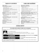
TABLEOF CONTENTS DRYER SAFETY ............................................................................ TABLEDES MATIERES 2 SECUR}TE DE LA SI_CHEUSE .............................................. 25 D'INSTALLATION ................................................ 27 INSTALLATION REQUIREMENTS .............................................. 5 Tools and Parts .......................................................................... 5 Location Requirements .............................................
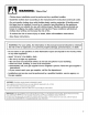
WARNING - Clothes dryer installation - ".isk ofFire" must be performed - Install the clothes dryer according by a qualified to the manufacturer's installer. instructions and local codes. - Do not install a clothes dryer with flexible plastic venting materials, if flexible metal (foil type) duct is installed, it must be of a specific type identified by the appliance manufacturer as suitable for use with clothes dryers.
In the State of Massachusetts, the following installation instructions apply: [] Installations and repairs must be performed by a qualified or licensed contractor, plumber, or gasfitter qualified or licensed by the State of Massachusetts. [] If using a ball valve, it shall be a T-handle type. [] A flexible gas connector, when used, must not exceed 3 feet.
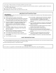
INSTALLATION REQUIREMENTS Gather the required tools and parts before starting installation. Read and follow the instructions provided with any tools listed here. Tools needed m 8" (20 mm) or 10" (25 mm) Pipe wrench m 8" (20 mm) or 10" (25 mm) adjustable wrench m Flat-blade screwdriver Explosion Hazard m Phillips screwdriver m Adjustable wrench that opens to 1" (25 mm) or 1" (25 mm) hex-head socket wrench Keep flammable materials and vapors, such as gasoline, away from dryer.
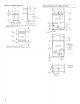
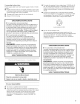
Minimum Installation Clearances Product Dimensions 27" (686 ram) dryer _I;r----27" _f max. oto 15" Closet _ (886 mm) 1 i d'q I (381 mm)* f ELECTRIC _ inl i (35.6 cm) O" door 11 (0 mm) 37" BACK VIEW o" (o mm) (940 mm) O"(0mm) _ -_ Recessed front view _4F-----1" (25 mm) Closet side view 13" (330 mm) 63/4 '' (152 mm) Additional clearances for wall, door, and floor moldings may be required or if external exhaust elbow is used. = _'GAS 4" (102 mm) dia.
Recommended Ground Method The dryer, when installed, must be electrically grounded in accordance with local codes or, in the absence of local codes, with the National Electrical Code, ANSl/NFPA 70, latest edition, or Canadian Electrical Code, CSA C22.1, and all local codes and ordinances. GROUNDING Electrical Shock Hazard Plug into a grounded 3 prong outlet. Do not remove ground prong. Do not use an adapter. Do not use an extension cord.
if using it is your responsibility [] To contact a qualified electrical installer. [] To be sure that the electrical connection is adequate and in conformance with the National Electrical Code, ANSl/NFPA 70-latest edition and all local codes and ordinances. The National Electrical Code requires a 4-wire power supply connection for homes built after 1996, dryer circuits involved in remodeling after 1996, and all mobile home installations.
If connecting bydirectwire: Power supply cablemustmatchpowersupply(4-wire or3-wire) andbe: [] Flexible armored cableornonmetallic sheathed copper cable (withground wire),protected withflexible metallic conduit. All current-carrying wiresmustbeinsulated. [] 10-gauge solidcopper wire(donotusealuminum). [] Atleast5ft (1.52m)long. GROUNDING INSTRUCTIONS [] For a grounded, cord-connected dryer: This dryer must be grounded.
Gas _iiiiiiii_i!:_!!iil; iiii_i:!ii?ili:i::iiiii? ¸ !i:!_%i?_!:ii:ii::'_!i!:_:_iiii_:_i_i_!!%:i:!!ii_ Supply Recommended Line method [] Provide a gas supply line of 1/2"rigid (IPS) pipe to the dryer location. Pipe joint compounds that resist the action of LP gas must be used. Do not use TEFLON _'t tape. With LP gas, piping or tubing size can be 1/2"minimum. Usually, LP gas suppliers determine the size and materials used in the system.
[] Installed in a confined area: If the dryer is installed in a confined area such as a bathroom or closet, provision must be made for enough air for combustion and ventilation. Check governing codes and ordinances or refer to the "Recessed Area and Closet Installation Instructions" in the "Location Requirements" section. Exhaust hood must be at least 12" (305 mm) from the ground or any object that may be in the path of the exhaust (such as flowers, rocks, or bushes).
Keep air openings free of dry cleaning fluid fumes. Fumes create acids which, when drawn through the dryer heating units, can damage dryers and loads being dried. [] [] A main vent can be used for venting a group of dryers. The main vent should be sized to remove 200 CFM of air per dryer. Large-capacity lint screens of proper design may be used in the main vent if checked and cleaned frequently.
INSTALLATIONINSTRUCTIONS- GASDRYER 1= With dryer in final position, place level on top of the dryer, first side to side; then front to back. If the dryer is not level, adjust the legs of the dryer up or down until the dryer is level. Excessive Weight Hazard Use two or more people to move and install dryer. Failure to do so can result in back or other injury. 1. Remove red cap from gas pipe. 2. Connect gas supply to dryer. Use pipe-joint compound resistant to the action of LR gas for gas connections.
INSTALLATIONINSTRUCTIONS-ELECTRICDRYER Power Supply Cord Method 1. Disconnect power. 2. Remove hold-down screw and the terminal block cover. - U.S. Only This dryer is manufactured with the neutral ground wire connected to the neutral (center) of the wiring harness at the terminal block. If local codes do not permit this type of connection, use "Four-wire connection" instructions. Use a UL-listed power supply cord rated 240 volt min., 30-amp and marked for use with a clothes dryer. A.
Power Supply Cord, Four-wire electrical connection: Remove the center terminal block screw. 6. Remove the appliance neutral ground wire from the external ground conductor screw. Fasten under center, silver-colored terminal block screw. A ............ ,_ _'_ ..... g 7. Connect the ground wire of the power supply cord to the external ground conductor screw. Tighten screw. B 8. Connect the neutral wire (white or center) of the power supply cord under the center screw of the terminal block.
Use this method where local codes permit connecting Power Supply Cord, Three-wire electrical connection: neutral ground wire to neutral wire: A ___j_ block screw. 6. 5. 7. A B ................. _ F .............................................................. Connect the neutral wire (white or center) of the power supplythe cord to the center, Loosen or remove center terminal silver-colored terminal screw of the terminal block. Tighten screw. Connect the other wires to outer terminal E .........
Direct Wire Method 1. 2. - U.S. Only Disconnect power. Remove hold-down screw and terminal block cover. A. External ground conductor screw B. Tab C. Terminal block cover D. Hold-down screw Fire Hazard Use 10 gauge copper wire. Use a UL listed strain relief. 3= Disconnect power before making electrical connections. Connect neutral wire (white or center wire) to center terminal (silver). install 3A" conduit connector into the hole below the terminal block opening.
Direct Wire, Three-wire electrical connection: Use this method where local codes permit connecting neutral ground wire to neutral wire: 5. Loosen or remove the center terminal block screw. 6. Three wire with ground wire: green or bare wire cut short. Wire is not used. Dryer is groundedthroughneutralconductor.
REVERSINGTHEDOORSWING(OPTIONAL) You can change your door swing from a right-side opening to a left-side opening, if desired. 6. D Be certain to keep cardboard spacer centered between doors. Reattach outer door panel to inner door panel so handle is on the side where hinges were just removed. 7. Attach door hinges to dryer door so that the larger hole is at the bottom of the hinge and the hinge pin is toward the door front. 1. Place towel (A) on top of dryer to protect surface. 2. Open dryer door.
ELECTRONIC CONTROL SETUP Electrical Shock Hazard Disconnect power before servicing, Replace all parts and panels before operating. Faiiure to do so can result in death or electrical shock, IMPORTANT E|ectrostatic Sensitive Discharge (=:SD) Electronics ESD problems are present everywhere. ESD may damage or weaken the electronic control assembly. The new control assembly may appear to work well after repair is finished, but failure may occur at a later date due to ESD stress.
DISPLAY SET-UP After the dryer has been installed and plugged in, the display will show '0 minutes.' [] The PERM.PRESS key pad will advance you from code to code. Single Load Models [] The DELICATES key pad will select or deselect options. AND COLORS m WHITES PRESS DELICATES m m PERM. CODES [] The WHITE AND COLORS key pad will change the code value. FOR PR MODELS: The set-up codes are the same as for the PD models except where noted.
IFIFI _UU MONEY COUNTER OPTION This option is either SELECTED'ON' or NOTSELECTED 'OFF'. Not Selected'OFF'. IFIFI IFIF OPTIONSTO USEiF SPECIALPRICINGIS SELECTED (continued): /LLLJLJ Selected'ON'. /. _ Pressthe DELICATESkey pad3 consecutivetimes to select 'ON' and3 consecutivetimes to remove(Not Selected'OFF'.) Counterresetsby going from 'OFF'to 'ON'. -_ Pressthe PERM.PRESSkey padonceto advanceto next code. This is the start hour,0-23 hours. SelectSTARTHOURby pressingthe WHITESANDCOLORSkeypad. cco_.
If cycle counter (9.0C) is selected, the following CL_. UU COIN SLIDE OPTION This option is either SELECTED'ON' or NOTSELECTED 'OFF'. Not Selected'OFF'. is true: 100 Represents the number of cycles in HUNDREDS. 1 02 = 200 200 Represents the number of cycles in ONES. 22`5= TOTAL = 225 cycles Selected'ON'. 0._ Pressthe DELICATESkey pad3 consecutivetimes for this selection.When coin slidemode is selected,set 'b.' equalto value of slidein nickels.Set '606' (REGULARCYCLEPRICE) and '3.
MAYTAG COMMERCIAL WASHEP DRYER, STACKED DRYE DRYE COMMERCIAL STACK LAUNDRY, AND MULTi-LOAD COiN OPERATED COMMERCIAL WASHERS AND DRYERS WAR NTY LIMITED WARRANTY ON PARTS For the first five years from the date of purchase, when this commercial appliance is installed, maintained and operated according to the instructions attached to or furnished with the product, Maytag brand of Whirlpool Corporation (thereafter "Maytag") will pay for factory specified parts or original equipment manufacturer parts to correc
P P P SECURITEDE LA SECHEUSE Votre securite et celle des autres est tres importante. Nous donnons de nombreux messages de s_curite importants dans ce manuel et sur votre appareil m_nager. Assurez-vous toujours lire tousles messages de s_curite et de vous y conformer. de Ce symbole d'alerte de s_curit_ vous signale les dangers potentiels de d_c_s et de blessures graves h vous et h d'autres.
AVERTISSEIViENT • Pour votre securite, les renseignements dans ce manuel doivent _tre observes pour reduire au minimum les risques d'incendie ou d'explosion ou pour eviter des dommages au produit, des blessures ou un deces. - Ne pas entreposer ou utiiiser de I'essence ou d'autres vapeurs ou liquides inflammables a proximite de cet appareil ou de tout autre appareil electromenager. -QUE FAIRE DANS LE CAS D'UNE ODEUR DE GAZ : ®Ne pas tenter d'allumer un appareil.
IMPORTANTES INSTRUCTIONS DE SI_CURITI_ AMERTISSEMENT • Pour r6duire le risque d'incendie, de choc 61ectrique ou de blessure Iors de I'utilisation de la s6cheuse, il convient d'observer certaines pr6cautions el6mentaires dont les suivantes : • Lire toutes les instructions • Ne pas placer des articles expos6s aux huiles de cuisson dans votre secheuse. Les articles contamin6s par des huiles de cuisson peuvent contribuer h une r6action chimique qui pourrait causer a la charge de s'enflammer.
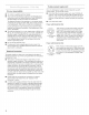
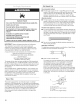
Distances de s_paration minimales 14" -- (358 mm) max. q 15" F- Porte du placard (381 mm)* inl i 0" (Omm) Risque d'explosion Garder les rnatieres et les vapeurs inflammables, que I'essence, loin de la secheuse. Le non=respect de ces instructions peut causer un d_c_s, une explosion ou un incendie. & gaz : Determiner les exigences des codes : Certains codes limitent ou prohibent I'instattation d'une secheuse dans un garage, un placard, ou une chambre _ coucher.
Dimensions du produit _-----27" - S_cheuse de 27" (686 ram) (686 mm) CABLE _ { ELECTRIQUE ' (35_4mm) / 37 II VUE ARRIERE (940 mm) Risque de choc _{ectrique 13 II 6_" (152mm) (339 mm) 4" (102 mm) dia. i/ CANALISATIONDE GAZ ' i =.m=_m 43/4" • BOUCHEDE 11A'' (32 mm) Brancher sur une prise & 3 aiv_oles (121 mm) l + { ....
M6thode recommand_e de liaison _ la terre Apr_s I'instatlation, la secheuse dolt _tre etectriquement reliee _ la terre conformement aux prescriptions des codes et r_gtements Iocaux; en t'absence de code local, respecter les prescriptions du code national en vigueur : National Electrical Code, ANSl/NFPA 70 (6dition la plus recente), ou Code canadien de t'electricit6, CSA C22.1, ainsi que cetles des codes et r_glements Iocaux.
Type de gaz La secheuse est 6quipee pour I'alimentation au gaz naturel. Elle est homologuee par CSA International pour t'atimentation avec des gaz de petrole liquefies (propane et butane), apr6s conversion appropriee. Ne pas entreprendre de convertir I'appareil pour l'utilisation d'un gaz different de celui indique sur la plaque signaletique sans d'abord consulter le fournisseur de gaz. Un technicien qualifie dolt effectuer la conversion.
[] Robinet d'arr_tnecessaire : Conformement auxprescriptions duNational FuelGasCode, ANSIZ223.1, ondoltinstaller unrobinet d'arr_tmanuel surla canalisation d'atimentation, &moins de6pi(1,8m)dela secheuse. AuCanada, lerobinet d'arr_tmanuel dolt_tre installe conformement auxprescriptions descodes d'instaltation B149 - CAN/CGA B149.1 etCAN/CGA B149.2. Lerobinet d'arr_tdolt_tresituedanslam_mepiecequela secheuse. IIdoltsetrouver &unemplacement quipermet une ouverture etunefermeture faciles.
Longueur du circuit d'_vacuation La Iongueur maximate du circuit d'evacuation depend du type de conduit utilise, du nombre de coudes et du type de bouche de decharge. La longueur maximate pour le circuit de conduit rigide est indiquee dans le tableau ci-apr_s. Longueur maximale conduits raccordes au conduit principal de part et d'autre devraient _tre disposes en quinconce pour que I'air evacue par une secheuse ne puisse perturber revacuation d'une autre secheuse.
# INSTRUCTIONSD'INSTALLATION-DEPLACEMENTDE LA SECHEUSEA SONEMPLACEMENTFINAL P La console renferme le panneau de contr61e electronique. Le panneau est configure & I'usine pour une duree de sechage de 45 minutes. Consulter la fiche technique situee h I'interieur de la ptinthe de la secheuse pour r_initiatiser la dur_e de s_chage ou pour d'autres options. 2. Retirer le ruban des coins avant de la secheuse. Ouvrir la secheuse et 6ter les sachets de de pi_ces et de documentation.
P INSTRUCTIONSffINSTALLATION-SECHEUSEA GAZ j!iii_,i::: iiii:ii _iii!_,_i_, ,_ii!!_ iii:,¸¸ iii(_'!ii :ii:iiii_ i!ii_ i_ii_!_ iii!} ii!i;ii:;i _ii_::i 1= Risque du poids excessif Une fois la secheuse h son emplacement final, placer un niveau sur le sommet de la secheuse, transversatement, puts dans le sens avant artiste. Si la secheuse n'est pas d'aplomb, ajuster les pieds pour modifier la hauteur et etabtir un bon aplomb de la secheuse.
P # INSTRUCTIONSffINSTALLATION-SECHEUSEELECTRIQUE Risque du poids excessif Utiliser deux ou plus de personnes pour d_placer et installer la s_cheuse, Risque de choc _lectrique Le non-respect de cette instruction peut causer une blessure au dos ou d'autre blessure. 1. A I'aide d'une bride de fixation de 4" (102 mm), relier le conduit d'evacuation _ la bouche d'evacuation de la secheuse. Si on utitise le conduit d'evacuation existant, s'assurer qu'il est propre.
INVERSIONDU SENS ffOUVERTUREDE LA PORTE (FACULTATIF) Le sens d'ouverture de la porte peut _tre change du c6te droit au c6te gauche, si desire. 6= D 1. Placer une serviette (A) sur le dessus de la secheuse pour proteger sa surface. 2. Ouvrir la porte de la secheuse. Oter les vis inferieures du c6te charni_re de la caisse (B). Desserrer (ne pas retirer) les vis superieures du c6te charni_re de la caisse.. 3.
P # REGLAGEDE LACOMMANDEELECTRONIQUE Remise en marche _ chaud apr_s une interruption de I'alimentation Risque de choc _lectrique D_connecter la source de courant _lectrique avant I'entretien.
AFFICHEUR Apr_s I'instatlation initiale et le branchement de I'appareit, I'afficheur pr6sente '0 MINUTES'. ModUles PR AND COLORS PRESS DEMCATES m m m WHITES PERM. IMPORTANT : Ne pas ouvrir la console avant d'avoir deconnect6 la secheuse detoute source d'energie. Pour acc6der au connecteur AA1 : -_ Debrancher la secheuse ou d6connecter la source de courant electrique. -_ Ouvrir la console, debrancher le connecteur AA1, refermer la console.
CnC _u u PRIX POUR PROGRAMME REGUUER _'_ Cecirepresente lenombredepi_cesde 0,25$ (piece1);regbgedans laplage0-39.(VoirVALEUR POUR PIECE 1 b.05)Pourfaireaugmenter lechiffreafficheentre0-39,appuyersurlatoucheWHITE AND COLORS. Configure #,I'usinepour6 piecesde0,25$ = 1,50$. MODELES PRSEULEMENT :Configur_ _.I'usinepour0 piece de 0,25$. OPTIONS DISPONIBLES SI UOPTION DEPRIXSPI_CIAL A ETESELECTIONNI:.'E : =_u _ PRIX POUR PROGRAMME SPECIAL _ m t.'T _-_.
JOUR POUR PRIX SP#;CIAL p3 In Cecirepr_sentelejourde lasemainesdectionn_,et lasdectionde la ratificationsp_cialepourcejour.Unchiffresuivide '0' indique quecetteoptionn'est passelectionn_epour lejourparticulier concern_(9.10).Unchiffresuivid'un 'S' indiquequecetteoption est selectionn_epour lejourconcern_(9.1S). Pourselectionnerlejourde la semaine(1-7),appuyersur latouche WHITES ANDCOLORS. Appuyerunelois sur latoucheDELICATES pour sdectionnerroptionde prixspecialpourchaquejourchoisi.
Si le compteur de programme {90.C) est s_lectionn_, est vrai : ce qui suit 100 Represente le nombre de programmes, en CENTAINES. 1 O2 = 200 200 Represente te nombre de programmes, en UNITERS. 2 2,5 = 25 COD¢:S DE DIAGNOSTIC Si un des ev6nements suivants est survenu avant qu'on accede au mode de parametrage, le code de diagnostic approprie sera visible sur I'afficheur. S_CHEUSES SIMPLES TOTAL = 225 programmes Cette information est "SEULEMENT AFFICHE_E";on ne peut I'effacer.
P GARANTIE DE LA LAVEUSE COMMERCIALE, DE LA SECHEUSE, DE LA SECHEUSE/SECHEUSE SUPERPOSEE, DE L'ENSEMBLE DE BUANDERIE COMMERCIAL SUPERPOSE, ET DES LAVEUSES ET SECHEUSES COMMERCIALES MULTI-CHARGE PAYANTES MAYTAG GARANTIE LIMITI_E SUR LES PIECES Pendant cinq ans &compter de la date d'achat, Iorsque cet appareil menager commercial est installe, utilis6 et entretenu conformement aux instructions jointes & ou fournies avec le produit, Maytag marque de Whirlpool Corporation (ci-apres designee "Maytag") paiera p
W10184578A W10184579A© 2008 All rights reserved. Tous droits r&serv&s. SP 10/2008 Printed in U.S.A. Imprim& aux E.-U.