INSTALLATION INSTRUCTIONS Original Instructions Commercial Gas or Electric Dryer Models MDE20PDAGW, MDE20PNAGW, MDE20MNAGW, MDE20CSAGW, MDG20PDAGW, MDG20PNAGW, MDG20MNAGW, AND MDG20CSAGW INSTRUCTIONS D’INSTALLATION Instructions d’origine Sèche-Linge À gaz ou Électrique à usage commercial Modèles MDE20PDAGW, MDE20PNAGW, MDE20MNAGW, MDE20CSAGW, MDG20PDAGW, MDG20PNAGW, MDG20MNAGW, AND MDG20CSAGW INSTRUCCIONES DE INSTALACIÓN Instrucciones originales Secadora a gas o eléctrica comercial Modelos MDE20PDAGW,
TABLE OF CONTENTS TABLE DES MATIÈRES DRYER SAFETY................................................................................3 FOR THE OWNER MAINTENANCE INSTRUCTIONS.................................................6 IF YOU NEED ASSISTANCE ........................................................6 FOR WHIRLPOOL AUTHORIZED SERVICE PERSON TOOLS & PARTS ..............................................................................7 DIMENSIONS/CLEARANCES ..................................................
DRYER SAFETY Your safety and the safety of others are very important. We have provided many important safety messages in this manual and on your appliance. Always read and obey all safety messages. This is the safety alert symbol. This symbol alerts you to potential hazards that can kill or hurt you and others. All safety messages will follow the safety alert symbol and either the word “DANGER” or “WARNING.
DRYER SAFETY ■■ It is recommended that the owner post, in a prominent location, instructions for the customer’s use in the event the customer smells gas. This information should be obtained from your gas supplier. ■■ Post the following warning in a prominent location. FOR YOUR SAFETY 1. DO NOT USE OR STORE GAS OR OTHER FLAMMABLE MATERIALS IN THIS APPLIANCE OR NEAR THIS APPLIANCE. 2. DO NOT SPRAY AEROSOLS IN THE VICINITY OF THIS APPLIANCE WHILE IT IS IN OPERATION. 3. DO NOT MODIFY THIS APPLIANCE.
DRYER SAFETY IMPORTANT SAFETY INSTRUCTIONS WARNING: To reduce the risk of fire, electric shock, or injury to persons when using the dryer, follow basic precautions, including the following: ■■ Read all instructions before using the dryer. ■■ This dryer is intended only for drying clothes and textiles ■■ ■■ ■■ ■■ ■■ ■■ ■■ ■■ ■■ ■■ ■■ ■■ ■■ ■■ ■■ ■■ ■■ that have been washed in water. Do not use for any other purpose.
MAINTENANCE INSTRUCTIONS ■■ Clean lint screen before and after each cycle. If dryer does not operate, check the following: ■■ Removing accumulated lint: ■■ Electrical supply is connected. From inside the dryer cabinet: Lint should be removed every 2 years or more often, depending on dryer usage. Cleaning should be done by a Whirlpool authorized person. From the exhaust vent: Lint should be removed every 2 years, or more often, depending on dryer usage.
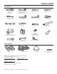
TOOLS & PARTS Tools Needed: 203 mm (8") or 254 mm (10") Pipe Wrench Torx† T-20† Security Screwdriver or Bit 203 mm (8") or 254 mm (10") Adjustable Wrench that opens to 25 mm ( 1") Flat-Blade Screwdriver 25 mm (1") Hex-Head 8 mm ( 5 ⁄ 16") Socket Wrench Socket Wrench Level Utility Knife 6 mm (1/4") Nut Driver Caulk Gun and Caulk Vent Clamps (for installing new exhaust vent) Flashlight (optional) 25 mm (1") Open-End Wrenches Pipe-Joint Compound Suitable for Gas Type Phillips Screwd
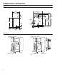
DIMENSIONS/CLEARANCES Dimensions Side View Back View 743 mm (291/4") 686 mm (27") 660 mm (26") Electric 343 mm (131/2") 210 mm (81/4") 38 mm (11/2") 25 mm (1") 914 mm (36") (electric models) Gas 140 mm (51/2") 343 mm (131/2") 191 mm (71/2") 1042 mm (41") 953 mm (371/2") (gas models) 102 mm (4" dia) 889 mm (35") 83 mm (31/4") 273 mm (103/4") 83 mm (31/4") Clearances Front View, Recessed Opening 356 mm (14" max) Side View, Recessed In Closet 356 mm (14" max) 76 mm (3"/3") 381 mm
DRYER INSTALLATION REQUIREMENTS (Australia and New Zealand – for full details of installation requirements refer to AS/NZS 5601.1) Location Requirements Your dryer can be installed in a basement, laundry room, or recessed area. This dryer is not intended for installation in a mobile home. Companion appliance location requirements should also be considered. IMPORTANT: Do not install or store the dryer where it will be exposed to the weather. Proper installation is your responsibility.
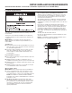
INSTALLING LEVELING LEGS AND COIN BOX The console houses the electronic control board. The board is factory set for a dry time of 30 minutes. Consult the tech sheet found inside the dryer toe panel to reset dry time and for other options. The card reading mechanism is not included, but is available from your usual industry sources. 1. Prepare dryer for leveling legs NOTE: Slide dryer onto cardboard or hardboard before moving to avoid damaging floor covering.
LEVELING Leveling your dryer properly reduces excess noise and vibration. 2. Grip dryer from top and rock back and forth, making sure all four legs are firmly on floor. Repeat, rocking dryer from side to side. If dryer rocks, go to Step 3 and adjust leveling legs. 1. Remove cardboard from beneath dryer. Place a level on top edges of dryer, checking each side and front. If not level, tip dryer and adjust legs up or down as shown in Step 3, repeating as necessary. 3.
ELECTRIC DRYER INSTALLATION REQUIREMENTS Electrical Requirements Electric Shock Hazard IMPORTANT: Observe all governing codes and ordinances. This dryer is supplied without an electric cord and plug. It must be connected by a Whirlpool authorized service person to a single-phase electricity supply at the voltage shown on the dataplate, using a suitable fixed wiring installation in accordance with local and national wiring regulations. n A 3-wire circular cord of minimum conductor size 2.
GAS DRYER INSTALLATION REQUIREMENTS Electrical Requirements EARTHING INSTRUCTIONS IMPORTANT: Observe all governing codes and ordinances. You will need a grounded electrical outlet located within 610 mm (2 feet) of either side of the dryer. This dryer is supplied/fitted with an electrical supply cord and plug. It should be connected to electrical supply socket at the voltage shown on the rating plate. The minimum supply fuse capacity should be 10A.
GAS DRYER INSTALLATION REQUIREMENTS Gas Supply Supply line requirements: IMPORTANT: Observe all governing codes and ordinances. In Australia and New Zealand, refer to AS/NZS 5601.1 – Gas Installations. Gas Supply Before installation, check that the local gas distribution conditions, nature of gas and pressure, and the adjustment of the appliance are compatible. Burner information will be found on the model/serial rating plate in the door recess of the dryer.
DRYER VENTING REQUIREMENTS Elbows: ■■ 45° elbows provide better airflow than 90° elbows. Good Better Clamps: ■■ Use clamps to seal all joints. WARNING: To reduce the risk of fire, this dryer MUST BE EXHAUSTED OUTDOORS. IMPORTANT: Observe all governing codes and ordinances. In Australia and New Zealand, refer to AS/NZS 5601.1 – Gas Installations. ■■ Exhaust vent must not be connected or secured with screws or other fastening devices that extend into interior of duct and catch lint. Do not use duct tape.
DRYER VENTING REQUIREMENTS Vent Hoods 102 mm (4") Diameter Exhaust Hoods Box Hood Louvered Hood Exhaust hood must be at least 305 mm (12") from the ground or any object that may be in the path of the exhaust (such as flowers, rocks, bushes, or snow). Angled Hood 12" min. 305 mm min. (305 mm) (12") Vent System Length Maximum Vent Length/Vent Connection Maximum length of vent system depends upon the type of vent used, number of elbows, and type of exhaust hood. 3.
DRYER VENTING REQUIREMENTS If an Exhaust Hood Cannot be Used Multiple Dryer Venting The outside end of main vent should have a sweep elbow directed downward. A main vent can be used for venting a group of dryers. The main vent should be sized to remove 5663 l/min. (200 CFM) of air per dryer. Large-capacity lint screens of proper design may be used in main vent if checked and cleaned frequently.
TECHNICAL SPECIFICATIONS – GAS DRYER 220–240V~50Hz 1ph 3A max. IP24 Clothes capacity: 9.0 kg max. Sound pressure level, Lpa: 58 dBA (uncertainty, Kpa: +/-10 dBA) Total mass: 68 kg max. Factory set for NATURAL GAS: Injector size: 2.2 mm Heat input gross: 5.9 kW Country: European Gas Category: Gas Flow Rate: CH, CZ, CY, ES, GB, GR, HR, IE, IT, PT, SI, SK, TR II2H3+ CY, CZ, DK, EE, FI, GR, HU, IT, NO, RO, SE, SK, TR II2H3B/P .562703 m3/hr 0.
COMPLETE INSTALLATION 1. Check the electrical requirements. Be sure that you have the correct electrical supply and the recommended earthing method. See “Electrical Requirements.” 2. Check that all parts are now installed. If there is an extra part, go back through the steps. 3. Check that you have all of your tools. 4. Dispose of/recycle all packaging materials. WARNING 6. Check dryer operation. Close dryer door. Set the cycle. Operating time will accumulate per number of coins.
REVERSING DRYER DOOR SWING (OPTIONAL) You can change your door swing from a right-side opening to left-side opening, if desired. Remove the Door Assembly 7. Be certain to keep cardboard spacer centered between doors. Reattach outer door panel to inner door panel so handle is on the side where hinges were just removed. 1. Place a towel or soft cloth on top of dryer or work space to avoid scratching of the surface. 2. Open dryer door. Remove bottom screws from cabinet side of hinges.
ELECTRONIC CONTROL SETUP INSTRUCTIONS (PD & PN MODELS ONLY) IMPORTANT Electrostatic Discharge (ESD) Sensitive Electronics ESD problems are present everywhere. ESD may damage or weaken the electronic control assembly. The new control assembly may appear to work well after repair is finished, but failure may occur at a later date due to ESD stress. n Use an anti-static wrist strap. Connect wrist strap to green ground connection point or unpainted metal in the appliance.
ELECTRONIC CONTROL SETUP INSTRUCTIONS (PD & PN MODELS ONLY) Control Set-up Procedures Set-Up Codes IMPORTANT: Read all instructions before operating. The fabric setting buttons along with the digital display are used to set up the dryer controls. The display can contain 4 numbers and/or letters and a decimal point. These are used to indicate the set-up codes and related code values available for use in programming the appliance. ■■ The NORMAL button will advance you from code to code.
ELECTRONIC CONTROL SETUP INSTRUCTIONS (PD & PN MODELS ONLY) Code Explanation 1. 00 MONEY COUNTER OPTION This option is either NOT SELECTED “OFF” or SELECTED “ON.” 1. 00 1. 0C Not Selected “OFF.” Selected “ON.” • Press the DELICATES button 3 consecutive times to select “ON” and 3 consecutive times to remove (Not Selected “OFF”). Counter resets by going from “OFF” to “ON.” 1. C0 Selected “ON” and not able to be deselected.
ELECTRONIC CONTROL SETUP INSTRUCTIONS (PD & PN MODELS ONLY) Code Explanation Code Explanation 7. 00 PECIAL PRICE START HOUR S NOTE: Uses military time or 24 hr. clock. b. 05 VALUE OF COIN 1 7. 00 This is the start hour; 0–23 hours. • Select START HOUR by pressing the HEAVY DUTY button. • Press the NORMAL button once to advance to next code. 8. 00 C. 20 VALUE OF COIN 2/VALUE OF DRYER TOP OFF SPECIAL PRICE STOP HOUR NOTE: Uses military time or 24 hr. clock. 8.
ELECTRONIC CONTROL SETUP INSTRUCTIONS (PD & PN MODELS ONLY) Code Explanation J. Cd PAYMENT MODE (COIN/DEBIT OPTION) J. Cd Both coin and debit selected. Press the DELICATES button 3 consecutive times to change this selection. J. C_ Coins selected, debit disabled. Press the DELICATES button 3 consecutive times to change this selection. J._d Debit Card selected, coins disabled. Press the DELICATES button 3 consecutive times to change this selection. J.
DRYER DISPOSAL MODEL NOMENCLATURE: MDG – Maytag Gas MDE – Maytag Electric 20 – Model Type Number 26 CS – Coin Slide MN – Timer Non-Pay PD – Coin Drop PN – Electronic Non-Pay A – Series Revision G – Global W – White
MAYTAG COMMERCIAL LAUNDRY LIMITED WARRANTY IF YOU NEED SERVICE: Contact your authorized Maytag Commercial Laundry distributor. To locate your authorized Maytag Commercial Laundry distributor, visit www.MaytagCommercialLaundry.com.