INSTALLATIONINSTRUCTIONS COMMERCIAL DRYER- Gas or Electric INSTRUCTIONSPOUR L'INSTALLATIOND'UNE SECHEUSECOMMERCIALE- A gaz ou (_lectrique TABLEDES MATIERES TABLE OF CONTENTS DRYER SAFETY ............................................................................ INSTALLATION REQUIREMENTS .............................................. Tools and Parts .......................................................................... Location Requirements ...........................................................
DRYERSAFETY Your safety and the safety of others are very important. We have provided many important safety messages in this manual and on your appliance. Always read and obey all safety messages. This is the safety alert symbol. This symbol alerts you to potential hazards that can kill or hurt you and others. All safety messages will follow the safety alert symbol and either the word "DANGER" or "WARNING.
WARNING: For your safety, the information in this manual must be followed to minimize the risk of fire or explosion, or to prevent property damage, personal injury, or death. - Do not store or use gasoline or any other appliance. or other flammable vapors and liquids in the vicinity of this - WHAT TO DO iF YOU SMELL GAS: ®Do not try to light any appliance. • Do not touch any electrical switch; do not use any phone in your building. = Clear the room, building, or area of all occupants.
iMPORTANT WARNING: SAFETY iNSTRUCTiONS To reduce the risk of fire, electric shock, or injury to persons when using the dryer, follow basic precautions, including the following: [] Read all instructions [] Do not place items exposed to cooking oils in your dryer. Items contaminated with cooking oils may contribute to a chemical reaction that could cause a load to catch fire.
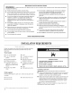
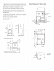
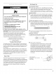
Recessed Area and Closet Installation instructions Product Dimensions This dryer may be installed in a recessed area or closet. For recessed area and closet installations, minimum clearances can be found on the warning label on the rear of the dryer. 27" (68.6 cm} dryer _.-=--27" (68.8 cm) =m| I I The installation spacing is in inches and is the minimum allowable. Additional spacing should be considered for ease of installation, servicing, and compliance with local codes and ordinances.
Recommended Ground Method _SHHHHHHHHHHHHHHHHHHHHHHHHHHHHHHHHH The dryer, when installed, must be electrically grounded in accordance with local codes or, in the absence of local codes, with the National Electrical Code, ANSl/NFPA 70, latest edition, or Canadian Electrical Code, CSA C22.1, and all local codes and ordinances. GROUNDING Electrical Shock Hazard Plug into a grounded 3 prong outlet. Do not remove ground prong. Do not use an adapter. Do not use an extension cord.
if using it is your responsibility [] To contact a qualified electrical installer. [] To be sure that the electrical connection is adequate and in conformance with the National Electrical Code, ANSl/NFPA 70-latest edition and all local codes and ordinances. The National Electrical Code requires a 4-wire power supply connection for homes built after 1996, dryer circuits involved in remodeling after 1996, and all mobile home installations.
If connecting by direct wire: Power supply cable must match power supply (4-wire or 3-wire) and be: [] Flexible armored cable or nonmetallic sheathed copper cable (with ground wire), protected with flexible metallic conduit. All current-carrying wires must be insulated. [] 10-gauge solid copper wire (do not use aluminum). [] At least 5 ft (1.52 m) long. GROUNDING To supply the required 4 wire, single phase, 120/240 volt, 60 Hz.
Gas _iiiiiiii_i!:_!!iil; iiii_i:!ii?ili:i::iiiii? ¸ !i:!_%i?_!/ii:ii::'_!i!:_:_iiii_:_i_i_!!%:i:!!ii_ Supply Recommended Line method [] Provide a gas supply line of 1/2"rigid (IPS) pipe to the dryer location. Pipe joint compounds that resist the action of LP gas must be used. Do not use TEFLON _'t tape with LP gas. Minimum tubing diameter for LP gas is 1/2".Usually, LP gas suppliers determine the size and materials used in the system.
[] Installed in a confined area: If the dryer is installed in a confined area such as a bathroom or closet, provision must be made for enough air for combustion and ventilation. Check governing codes and ordinances or refer to the "Recessed Area and Closet Installation Instructions" in the Location Requirements section. Exhaust hood must be at least 12" (30.5 cm) from the ground or any object that may be in the path of the exhaust (such as flowers, rocks, or bushes).
Keep air openings free of dry cleaning fluid fumes. Fumes create acids which, when drawn through the dryer heating units, can damage dryers and loads being dried. [] [] A main vent can be used for venting a group of dryers. The main vent should be sized to remove 200 CFM of air per dryer. Large-capacity lint screens of proper design may be used in the main vent if checked and cleaned frequently.
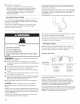
INSTALLATIONINSTRUCTIONS- GASDRYER 1= With dryer in final position, place level on top of the dryer, first side to side; then front to back. }f the dryer is not level, adjust the legs of the dryer up or down until the dryer is level. Excessive Weight Hazard Use two or more people to move and install dryer. Failure to do so can result in back or other injury. 1. Remove red cap from gas pipe on back of dryer. 2. Connect gas supply to dryer.
INSTALLATION INSTRUCTIONS-ELECTRICDRYER Power Supply Cord 2. Remove the hold-down 3. Install strain relief. screw and terminal block cover. A. Neutral ground wire B. External ground conductor screw C. Center, silver-colored terminal block screw D. Terminal block cover and holddown screw Fire Hazard Use a new UL listed 30 amp power supply cord. Use a UL listed strain relief. Disconnect power before making electrical connections.
Power supply cord strain relief: [] [] Remove the screws from a 3/4"(1.9 cm) UL listed strain relief (UL marking on strain relief). Put the tabs of the two clamp sections into the hole below the terminal block opening so that one tab is pointing up and the other is pointing down, and hold in place. Put power supply cord through the strain relief. Be sure that the wire insulation on the power supply cord is inside the strain relief.
3. Power supply cord, 4=wire connection: Connect ground wire (green or bare) of power supply cord to external ground conductor screw. Tighten screw. IMPORTANT: A 4-wire connection is required for mobile homes and where local codes do not permit the use of 3-wire D connections. B F .................... _ ............................................................... ::; E g J j_ S J c G E _ A. 4-wire receptacle (NEMA type 14-30R) B. 4-prong plug C. Ground prong D. Neutral prong E.
Power supply cord, 3-wire connection: B Use where local codes permit connecting cabinet=ground conductor to neutral wire. 1. Loosen or remove center silver-colored terminal block screw. D E 2. Y A G F Connect neutral wire (white or center wire) of power supply cord to the center, silver-colored terminal screw of the terminal block. Tighten screw. 3. Connect the other wires to outer terminal block screws. Tighten screws. A. 3-wire receptacle (NEMA type 10-30R) B. 3-wire plug C. Neutral prong D.
Direct Wire Method Direct wire cable must match power supply (4-wire or 3-wire) and be: = U.S. Only [] Flexible armored cable or nonmetallic sheathed copper cable (with ground wire), protected with flexible metallic conduit. All current-carrying wires must be insulated. [] 10-gauge solid copper wire (do not use aluminum). [] At least 5 ft. (1.52 m) long. 1. 2. Disconnect power. Remove hold-down screw and terminal block cover. D A. Neutralgroundwire B. Externalground conductorscrew C.
DirectWire, 4-wireconnection: A IMPORTANT: A 4-wire connection is required for mobile homes and where local codes do not permit the use of 3-wire connections, E Direct wire cable must have 5 ft (1.52 m) of extra length so dryer can be moved if needed. Strip 5" (12.7 cm) of outer covering from end of cable, leaving bare ground wire at 5" (12.7 cm). Cut 11Z2 '' (3.8 cm) from 3 remaining wires. Strip insulation back 1" (2.5 cm). Shape ends of wires into a hook shape.
Direct wire, 3=wire connection: A ri l C Use where local codes permit connecting cabinet-ground conductor to neutral wire. Direct wire cable must have 5 ft (1.52 m) of extra length so dryer can be moved if needed. Strip 31_" (8.9 cm) of outer covering from end of cable. Strip insulation back 1" (2.5 cm). If using 3-wire cable with ground wire, cut bare wire even with outer covering. Shape ends of wires into a hook shape. t?., _ c_ .......................... k_ ",i', ,; _/j:::: _s,_c_ :::_J .......
1. 2. Using a 4" (10.2 cm) clamp, connect vent to exhaust outlet in dryer. If connecting to existing vent, make sure the vent is clean. The dryer vent must fit over the dryer exhaust outlet and inside the exhaust hood. Make sure the vent is secured to exhaust hood with a 4" (10.2 cm) clamp. Move dryer into final position. Do not crush or kink vent. Make sure dryer is level. 1. With dryer in final position, place level on top of the dryer, first side to side; then front to back.
REVERSINGTHE DOORSWING You can change your door swing from a right-side opening to left-side opening, if desired. Place a towel or soft cloth on top of the dryer or work space to protect the surface. 1. 1. Use a small flat-blade screwdriver to remove 2 plug strips from the inner door. Slide the head of the screwdriver under the plugs, being certain not to scratch the inner door surface. Lift up. Remove the 4 screws that hold the door hinge on the front panel of the dryer. ® 2.
1. Use a small flat-blade screwdriver to remove plug strip from the dryer door opening. Slide the head of the screwdriver under the strip, being sure not to scratch the dryer surface. Lift up. 2. Remove the strike using a #2 Phillips screw driver. 3. Install strike on the opposite side. 1. Reattach door to dryer front panel with the 4 screws. f--.. @ A. Dryer front panel B. Door assembly 2. Check for fingerprints on the inside of the glass. Clean glass if necessary. A, A.
WHIRLPOOLCOMMERCIALLAUNDRYWARRANTY: CAM2752,CEM2750,CGM2751,CAM2762,CEM2760,CGM2761,CSP2760, CSP2761,CEW91OO, CGW91OO, CHW9900 LiMiTED WARRANTY For the first three years from the date of purchase, when this commercial appliance is installed, maintained, and operated according to the instructions attached to or furnished with the product, Whirlpool Corporation (thereafter "Whirlpool") will pay for factory specified parts or original equipment manufacturer parts to correct defects in materials or workmanship
P P P SECURITEDE LA SECHEUSE Votre securite et celle des autres est tres importante. Nous donnons de nombreux messages de s_curite importants dans ce manuel et sur votre appareil m_nager. Assurez-vous toujours lire tousles messages de s_curite et de vous y conformer. de Ce symbole d'alerte de s_curit_ vous signale les dangers potentiels de d_c_s et de blessures graves h vous et h d'autres.
AVERTISSEIViENT • Pour votre securite, les renseignements dans ce manuel doivent _tre observes pour reduire au minimum les risques d'incendie ou d'explosion ou pour eviter des dommages au produit, des blessures ou un deces. - Ne pas entreposer ou utiiiser de I'essence ou d'autres vapeurs ou liquides inflammables a proximite de cet appareil ou de tout autre appareil electromenager. -QUE FAIRE DANS LE CAS D'UNE ODEUR DE GAZ : ®Ne pas tenter d'allumer un appareil.
IMPORTANT : L'installation du gaz dolt se conformer aux codes Iocaux, ou en I'absence de codes Iocaux, au code canadien d'installation B149.1 du gaz naturel ou du propane. La secheuse dolt 6tre 61ectriquement reliee h la terre conformement canadien de I'electricit6, CSA C22.1. aux codes Iocaux, ou en I'absence de codes Iocaux, au Code EXIGENCESD'INSTALLATION Rassembter tes outils et pi_ces necessaires avant de commencer I'instatlation.
Distances de s_paration minJmales (35,6 14" c m)_ o o 15" (38,1 cm)* t Dimensions du produit - S_cheuse de 27" (68,6 cm) max. I-" Porte du placard _---------1_. r-%::::::_3-- H .=_--<'_==27"(68.6 cm) ! ! "[ N ,.... , 5" (5,2 cm) f CABLE ELECTRIQUE 0" (0 cm) 0" (O cm) N I_ ........II ......
Methode recommand_e de liaison _ la terre Apr_s I'installation, la secheuse dolt _tre etectriquement reliee & la terre conformement aux prescriptions des codes et r_glements Iocaux; en I'absence de code local, respecter les prescriptions du code national en vigueur : National Electrical Code, ANSl/NFPA 70 (edition la plus recente), ou Code canadien de I'electricite, CSA C22.1, ainsi que cetles des codes et r_glements Iocaux. Risque de choc _lectrique Brancher sur une prise & 3 alv_oles reli_e b la terre.
_iii!iii_iii::i_=_!ii!;_;J ¸_:;iii!!!i_i::!::ii!!i_i::ii0!!:i_!;; di_ii,iii!_,_::i_i:_:'i_i:ii!ii;ii_:!!_!i; ...... iii!ii;_0,_;;!ii!i _']i)_;_!i)_iiiiil;ii_i:iir:iiiiii:i(!_ii;ii:,:i_ ;!)ii,_(Y,ii;;!iii!_!:i!!_i_iiiz_i!_!!% iil;_ INSTRUCTIONS DE LIAISON ,_ LA TERRE I Pour une s_cheuse reli_e & la terre et connect_e par un cordon : Cette s_cheuse doit @re reli_e & la terre.
Type de gaz La secheuse est 6quipee pour I'alimentation au gaz naturel. Elle est homologuee par CSA International pour t'atimentation avec des gaz de petrole liquefies (propane et butane), apr6s conversion appropriee. Ne pas entreprendre de convertir I'appareil pour l'utilisation d'un gaz different de celui indique sur la plaque signaletique sans d'abord consulter le fournisseur de gaz. Un technicien qualifie dolt effectuer la conversion.
[] Robinet d'arr_t necessaire : Conformement aux prescriptions du National Fuel Gas Code, ANSi Z223.1, on dolt installer un robinet d'arr_t manuel sur la canalisation d'atimentation, & moins de 6 pi (1,8 m) de la secheuse. Au Canada, le robinet d'arr_t manuel dolt _tre installe conformement aux prescriptions des codes d'instaltation B149 - CAN/CGA B149.1 et CAN/CGA B149.2. Le robinet d'arr_t dolt _tre situe dans la m_me piece que la secheuse.
Longueur du circuit d'_vacuation La longueur maximate du circuit d'evacuation depend du type de conduit utitise, du nombre de coudes et du type de bouche de decharge. La Iongueur maximate pour le circuit de conduit rigide ou flexible est indiquee dans le tableau ci-apr_s. Longueur maximale du conduit Chaque conduit d'evacuation devrait penetrer dans le conduit principal _ un angle pointant dans la direction du debit d'air.
INSTRUCTIONSD'INSTALLATION - GLISSIEREET CAISSEA MONNAIE La console inclut la minuterie (accumulation bouton et bras de manceuvre. 3. Prendre deux corni6res de carton de I'emballage et les placer sur le plancher _ I'arri_re de la secheuse. Saisir fermement la secheuse et la placer doucement en appui sur la face artiste, sur les corni_res de carton. 4. Prendre I'un des pieds et identifier la marque en losange dans le filetage. Ce repere indique jusqu'o_ le pied dolt 6tre visse dans le trou.
Jii_ _z:; i!iit _iii!z_ '_i; '¸_,_iti!_: ¸t" i!:_:'_ !iitliii_ _!t;i; _i_ ii_::!_, iilil:ili:_ iii;_ii ,i::i_ t_i_ 1= Une fois la secheuse & son emplacement final, placer un niveau sur le sommet de la secheuse, transversatement, puis darts le sens avant arri@e. Si la secheuse n'est pas d'aplomb, ajuster les pieds pour modifier la hauteur et etabtir un bon aplomb de la secheuse. Risque de choc 61ectrique Brancher sur une prise b 3 alveoles reli6e b la terre.
INSTRUCTIONSffINSTALLATION-SECHEUSEELECTRIQUE 1. A I'aide d'une bride de fixation de 4" (10,2 cm), relier le conduit d'evacuation h la bouche d'evacuation de ta secheuse. Si on utilise le conduit d'evacuation existant, s'assurer qu'il est propre. Le conduit d'evacuation de la secheuse dolt _tre fixe sur la bouche d'evacuation de la secheuse et dans le clapet d'evacuation. S'assurer que le conduit d'evacuation est fixe au clapet d'evacuation h I'aide d'une bride de fixation de 4" (10,2 cm).
Inversion du sens d'ouverture de |a porte Le sens d'ouverture de la porte peut _tre change du c6te droit au c6te gauche, si desire. 4. Soutever la partie interne de la porte hors de la pattie externe. Placer une serviette ou un linge doux sur le dessus de la 5. Faire pivoter la pattie exteme de 180°. secheuse ou du plan de travail pour proteger la surface. 180 ° (iiiiii:¸¸'¸ ii}: i! !ii i 1. Enlever les 4 vis qui maintiennent la charni_re de la porte sur le panneau avant de la secheuse. @ 1.
2. Oter les 4 vis qui fixent la charni@e de la porte interne et deptacer la charni@e de I'autre c6te. Reinstatter les 4 vis. 1. Utitiser un petit tournevis & lame plate pour enlever la tringle des pitons d'obturation des trous dans I'ouverture de la porte de la secheuse. Faire glisser la t_te du tournevis sous les tringles, en veillant & ne pas @after la surface de la secheuse. Soulever. 2. Utitiser un tournevis de s6curit6 TORX_'T-20 pour 6ter la g&che. 3. Inserer la g_che sur le c6te oppose. A A.
P # REGLAGEDE COMMANDEELECTRONIQUE Voir la fiche technique pour plus d'information du reglage. _propos INSTRUCTIONSD'ENTRETIEN Instructions d'entretien : Si vous avez besoin d'aide : I Nettoyer le filtre & charpie apr6s chaque utitisation. Comment enlever la charpie accumutee : * De I'interieur de la secheuse : II faut retirer la charpie tousles 2 ans ou plus souvent, selon I'utitisation de [a secheuse. Le nettoyage dolt 6tre effectue par une personne quatifiee.
GARANTIEDE LABUANDERIECOMMERCIALEWHIRLPOOL: CAM2752,CEM2750,CGM2751,CAM2762,CEM2760,CGM2761,CSP2760, CSP2761, CEW91OO,CGW91OO,CHW9900 GARANTIE LIMITI_E Pendant les trois premieres annees & compter de la date d'achat, Iorsque cet appareil commercial est installe, utilise et entretenu conformement aux instructions jointes b_ou fournies avec le produit, Whirlpool Corporation (ci-apres designee "Whirlpool") paiera pour les pieces specifiees par I'usine ou les pi_ces d'origine du fabricant de t'appareil pour cor
W10184516A W10184517A-SP © 2008 All rights reserved. Tous droits r&serv&s. 40 06/2008 Printed in U.S.A. Imprim& aux E.-U.