MDG (ALL) INSTALLATION INSTRUCTIONS
PLEASE READ ALL INSTALLATION INSTRUCTIONS AND REQUIREMENTS BEFORE INSTALLING. AWARNING: For your safety the information in this manual must be followed to minimize the risk of fire or explosion or to prevent property damage, personal injury or loss of life. _ATTENTION: Pour votre s_curit6, suivre les indications donn6es dans ce manuel afin de r_duire les risques d'incendie ou d'explosion et d'_viter dommages materiels, blessures et d6c_s.
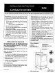
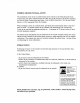
Read this before you start... TOOLS needed for installation Joint Compound (gas on_y) •Cutting Knife S( •Nut Drivers .Pipe Wrench *Level _ = <_ •Screw Driver (Standard) •Duct Tape •Crescent Wrench ITEMS PROVIDED @@ X @@ Electric Dryer OnLy Proper installation is the responsibility Gas Dryer Oniy of the owner. HOWEVER, SERVICE CALLS PERFORMED AS A RESULT OF POOR SETUP, ADJUSTMENT, AND CONNECTION ARE THE RESPONSIBILITY OF THE INSTALLER. Make sure you have everything !. GROUNDED 2. POWER 3.
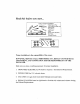
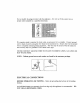
mt mum -T _!=_minimum i_._ IMPORTANT ,l, Base Exhaust TO INSTALLER PLEASE READ TIlE FOLLOWING INSTRUCTIONS CARSEFUT._LY BEFORE STARTING TO INSTALL TI_ DRYER. THESE INSTRUCTIONS SHOL_LD RETAINED FOR FUTURE REFERENCE. REMOVE THE DOOR FROM ALL DISCARDED APPLIANCES TO AVOID THE DANGER OF A CHILD SUFFOCATING. LOCATION SUCH BE AS DRYERS CONSIDERATIONS The dryer should be located to permit adequate room in front for loading ficient room behind the dryer for the exhaust system.
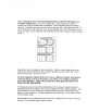
ALCOVE OR CLOSET INSTALLATION WARNING - The dryer must be exhausted to the outside to reduce the risk of fire when installed in an alcove or closet. An appliance same closet. installed in a closet shall have no other fuel-burning appliance installed in the Each opening area in the door must have a minimum of 36 square inches. These openings must not be obstructed. (Louvered door with equivalent air opemng is acceptable). CLOSET DO_R_ L olo -f ]÷ --36 S_ inch 17" 8°_° ©_k _2 0" o2.
MOBILE HOME INSTALLATION The installation of the dryer in mobile homes must conform to the Manufactured Home Construction and Safety Standard Title 24 CFR, Part 32-80 (formerly the Federal Standard for Mobile Home Construction and Safety, TNe 24 HUD (Part 280), 1975 for the United States), or CSA Standards Z240 (for Canada). When installing a dryer in a mobile home, provisions for anchoring the dryer to the floor must be made. An anchor bracket kit is available with instructions (see Accessories).
USE A MIN/MUM OF 4 INCH DIAMETER RIGID ALUM!NqJM OR RIGID GAL- VANIZED STEEL DUCT. Do not use smaller duct. Ducts larger than 4 inches in diameter can result in increased lint accumulation. Lint accumulation should be cleaned regularly. If flexible metal duct must be used, use the type with a stiff sheet metal wall. do not use flexibIe duct with a thin foiI wall. Serious blockage can result if flexible metal duct is bent too sharp.
GAS REQUIREMENTS Use only Natural or LP gases. THE INSTALLATION MUST CONI_ORM WITH LOCAL CODES, OR IN THE ABSENCE OF LOCAL CODES, WITH THE NATIONAL FUEL GAS CODE ANSI/Z223.1, LATEST REVISION (FOR THE UNITED STATES), OR WITH TIlE CAN/CGA-B149 INSTALLATION CODES (FOR CANADA). Gas dryers are equipped with a burner orifice for operation on NATURAL gas.
ELECTRICAL NOTE: REQUIREMENTS Wiring diagram is located inside the control console. prevent urlr_ecassary risk of fire, electrical shock or WARNING - To personal injury, all wiring and grounding must be done in accordance with focal codes, or in the absence of local codes, with the Na_ tional Electrical Code, ANSI/ NFPA (for the Untted States) or the Canadian Electrical code CSA C22,1 (for Canada). GROENDING This dryer must be grounded.
Do not modify the plug provided with the appliance proper outlet installed by a qualified electrician. K a separate round wire to back of unit by using wire to a suitable the accessory NEVER HOT CONNECT by local the wire ground GROUND codes, found connection. an accessory kit is available. in the accessory The COLD metal water WIRE TO PLASTIC wire kit. Connect Secure may be secured have other with a ground end of ground the clamp (in pipe.
Do not modify the plug provided with the appliance- if it will not fit the outlet, havea proper outlet installed by a qualified electrician. If a separateround is required by local codes,an accessorykit is available. Connectground wire to back of unit by using the wire found in the accessorykit. Secureother endof ground wire to a suitableexternal ground connection. The wire may be securedwith the clamp(in the accessorykit) to a groundedCOLD metal water pipe.
GAS MODELS A 120 volt, 60 Hz electrical ELECTRIC of electrical The electrical supply circuit both sides of the line. U.S. with a 15 ampere fuse or circuit breaker is required. MODELS To avoid the possibility 2-wire circuit. If a power supply, shock, the dryer must not be connected should be fused through cord is used, the cord should be plugged a 30 ampere to a 120 volt fuse or circuit breaker on into a 30 ampere receptacle.
CANADIAN All Canadian NOTE: MODELS models are shipped with the power cord attached. It is not permissible to convert a dryer in Canada to 208 volts. ADDITIONAL INFORMATION - 50 HERTZ OPERATION This Maytag dryer model is manufactured for operation on 60 Hz AC approved electrical service. This model is not designed for use on 50 Hz AC electrical service and conversion of the product from 60 to 50 HZ operation is not recommended.
REPLACEMENT PARTS AND ACCESSORIES If your dryer requires replacement parts or accessories, contact the dealer from who you purchased your dryer or Maytag Customer Service, PO Box 2370, Cleveland, TN 373202370. Phone 423-472-3333, for information on the nearest authorized Maytag Parts Distributor. TO INSTALL ..... 1. Move dryer to an appropriate location for installation.
3. Loosen the leveling locking nuts and install the vinyl feet. 4. Set the dryer back in an upright position. 5. Review the exhaust section in the previous section before installing the exhaust system. Install the ductwork from the dryer to the exhaust hood. The crimped end of the duct sections must point away from the dryer. DO NOT use sheet recta1 screws when assembling ducting. These joints should be taped. Never use plastic flexible exhaust material.
6. GAS DRYER SECTION To Make Gas Connection tions. 1. Remove , . , - Review gas requirements the pipe thread protective in previous section of these instruc- cap. Apply pipe joint compound or about 1 1/2 wraps of Teflon tape over atl threaded connections. NOTE: Pipe joint compound must be resistant to the action of an}, liquefied petroleum gas. Connect the gas supply to the dryer.
ELECTRIC DRYER SECTION To Make the Electrical Connection tion of these instructions. - Review the electrical requirements in the previous sec- IMPORTANT - The dryer frame is grounded to the neutral conductor at the terminal block. If the dryer is installed in a mobite home, or if local codes do not permit grounding through the neutral, refer to 4 WIRE SYSTEM CONNECTION. Remove the terminal block cover plate. Insert the power cord with a U.L.
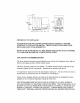
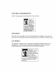
Connect the neutral (white) conductor of the cord to the center (silver colored) post of the terminal block. Connect the grounding (green) wire of the cord to the terminal block support using the ground strap screw. Connect the red and black wires of the cord to the outer posts of the terminal block. Be sure the termini block nuts are on tight. Secure the power cord in position. strain relief screw(s) in order to clamp the strain relief to the cord. Tighten the Replace the terminal block cover.
C 3-Wire System o Neutral Post _.. Ground Strap / / Neutral / Stra;n Relief / - krnproper connection of the equipment -grounding conductor can result in a risk of electrical shock. Check with a qualified electrician or service man if you are in doubt as to whether the appliance is properly grounded. Do not modify the plug provided with the appliance - if it will not fit the outlet, have a proper outlet installed by a qualified electrician.
7. With a level, checkthe dryer, andmakenecessaryadjustmentsto the leveling legs. Once level, tighten the leveling leg locking nuts with a wrench. 8. The dryer door direction can be reversed. 1. If the dryer is plugged in, unplug the dryer from the electrical service. 2. Removethe hinge hole coversandcrews. Move the door catch cover to the oppositeside. 3. While supportingthe door, remove2 screwsin the hinges that secure the hinges to the cabinet. 4.
9. At this time, make sure all gas, exhaustandelectricalconnectionsare complete. Plug dryer in, and checkoperationby using the checklistbelow. 10. (GAS MODELS ONLY) - The burner may not ignite initially dueto air in the gaslille. Allowing the dryer to operateon a heat settingwitl purge the line. If the gasdoesnot ignite within five minutes, turn tile dryer off andwait 5 minutes. Be surethe gassupply to the dryer hasbeenturned on. In order to confirm gasignition, checkthe exhaustfor heat.