
Installation guide
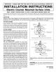

Unitsshownin figures1 and 2 may be installedin
combustiblecountertopandmustbespacedat least(1"
from)combustiblesidesandrearwallabovecountertop.
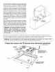
Unitshowninfigure3 maybeinstalledin combustible
countertopandadjacentto (0"from)combustiblesides
andrearwallabovecountertop.
DimensionA =30-inchesminimumclearancebetweentop
ofthecookingsurfaceandthebottomof anunprotected
woodor metalcabinet,orA = 24-inchesminimumwhen
bottomofwoodor metalcabinetisprotectedbynotless
than1/4inchflameretardantmillboardcoveredwithnot
lessthanno.28msgsheetsteel,.015inchstainlesssteel,
.024inchaluminumor .020inchcopper.
"Toeliminatethehazardofreachingoverheatedsurface
units,cabinetstoragespacelocatedabovethesurface
unitsshouldbe avoided.If cabinetstorageis to be
provided,thehazardcanbereducedbyinstallingarange
hoodthat projectshorizontallya minimumof 5-inches
beyondthebottomofthecabinets."
CAUTION: SOMECABINETSAND BUILDING
MATERIALSARENOTDESIGNEDTOWITHSTAND
THE HEATPRODUCEDBY THE NORMALSAFE
OPERATIONOF A LISTEDAPPLIANCE,DIS-
COLORATIONORDAMAGE,SUCHASDELAMINA-
TION,MAYOCCUR,
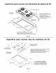
COUNTER
TOP BASE
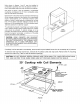
If cooktop is to be secured to countertop, remove main top and attach burner box to countertop at (4) corners.
To remove main top from burner box, remove all (4) surface units and drip bowls. Remove the (4) mounting
screws from main top. (Tabs on side of element openings.)
CAUTION:DO NOT REMOVE GREEN GROUND WIRE FROM MAIN TOP WHEN REPLACING MAIN
TOP; USECAUT ONTOBE SURE W RESARE NO NCHED UNDER SWTCH SH ELD
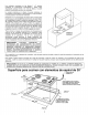
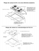
30" Cooktop with Coil Elements
DEPTH
FRONT OI
UNIT
LEADS
3/8" FLEXIBLECABLE3' MIN.
FURNISHEDAND
INSTALLEDBY MANUFACTURER
(CONNECTTO240/120-VOLT
ELECTRICALSERVICE.)
C 219-1tA
MtN. PLUS CLEARANCE
INSIDE FOR RIGHT ANGLE
CONDUIT AND WIRE
FIGURE1