
Owners Manual
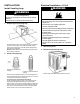
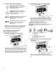
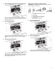
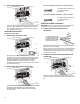
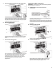

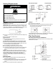
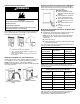
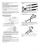
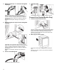
Table Of Contents
- Dryer Safety
- Dryer Safety
- Dryer Maintenance and Care
- Cleaning the Dryer Location
- Cleaning the Dryer Interior
- Removing Accumulated Lint
- Cleaning the Lint Screen
- Changing the Drum Light (on some models)
- Check Your Vent System for Good Airflow
- Maintain Good Airflow
- Nonuse, Storage, and Moving Care
- Special Instructions for Steam Models
- Installation Instructions
- Requirements
- Tools and Parts
- Location Requirements
- Electrical Requirements – U.S.A.
- Electric Requirements – Canada
- Installation
- Install Leveling Legs
- Electrical Installation – U.S.A.
- Venting Requirements
- Plan Vent System
- Install Vent System
- Connect Inlet Hoses
- Connect Vent (Vented Models Only)
- Level Dryer
- Complete Installation Checklist
- Sécurité de la sécheuse
- Sécurité de la sécheuse
- Entretien et réparation de la sécheuse
- Nettoyage de l’emplacement de la sécheuse
- Nettoyage de l’intérieur de la sécheuse
- Retrait de la charpie accumulée
- Nettoyage du filtre à charpie
- Changement de l’ampoule d’éclairage du tambour (sur certains modèles)
- Vérification d’une circulation d’air adéquate pour le système d’évacuation
- Pour maintenir une bonne circulation d’air
- Précautions à prendre lorsque l’appareil n’est pas utilisé, est entreposé ou déménagé
- Instructions spécifiques pour les modèles vapeur
- Instructions d’installation
- Spécifications
- Outils et pièces
- Exigences d’emplacement
- Spécifications électriques – É.-U.
- Spécifications électriques – Canada
- L’installation
- Installation des pieds de nivellement
- Installation Électrique - U.S.A
- Exigences concernant l'évacuation
- Planification des circuits de conduits
- Installation du conduit d’évacuation
- Raccordement des tuyaux d’alimentation
- Raccorder le conduit d’évacuation (sur les modèles avec conduit seulement)
- Réglage de l’aplomb de la sécheuse
- Liste de vérification pour installation terminée

18
Optional exhaust installations:
WARNING
Fire Hazard
Cover unused exhaust holes with a manufacturer’s
exhaust cover kit.
Contact your local dealer.
Failure to follow these instructions can result in death,
fire, electrical shock, or serious injury.
Some models can be converted to exhaust out the right side, left
side, or through the bottom. If you prefer, you may contact your
local dealer to have the dryer converted.
A. Standard rear offset exhaust installation
B. Left- or right-side exhaust installation (available only on
select 27"-wide models).
C. Bottom exhaust installation (available only on select 27"-
wide models).
Alternate installations for close clearances
Venting systems come in many varieties. Select the type best for
your installation. Two close-clearance installations are shown.
NOTE: The following kits for close-clearance alternate
installations are available for purchase. Refer to Quick Start Guide
for contact information.
Over-The-Top installation
(also available with one offset
elbow)
Periscope installation
Special provisions for mobile home installations:
Exhaust vent must be securely fastened to a noncombustible
portion of the mobile home and must not terminate beneath the
mobile home. Terminate exhaust vent outside.
Determine vent path:
n Select route that will provide
straightest and most direct path
outdoors.
n Plan installation to use fewest
number of elbows and turns.
n When using elbows or making
turns, allow as much room as
possible.
n Bend vent gradually to avoid
kinking.
n Use as few 90° turns as
possible.
Determine vent length and elbows needed for best
drying performance:
n Use following “Vent System Chart” to determine type of vent
material and hood combinations acceptable to use.
NOTE: Do not use vent runs longer than those specified in
“Vent System Chart.” Exhaust systems longer than those
specified will:
n Shorten life of dryer.
n Reduce performance, resulting in longer drying times and
increased energy usage.
The “Vent System Chart” provides venting requirements that will
help achieve best drying performance.
Vent System Chart
Number of 90°
turns or elbows
Type of vent
Box/louvered or
Angled hoods
0
Rigid metal 64 ft. (20 m)
1
Rigid metal 54 ft. (16.5 m)
2
Rigid metal 44 ft. (13.4 m)
3
Rigid metal 35 ft. (10.7 m)
4
Rigid metal 27 ft. (8.2 m)
NOTE: Side and bottom exhaust installations have a 90º turn
inside the dryer. To determine maximum exhaust length, add one
90º turn to the chart.
Vent System Chart (Long Vent Models)
Number of 90°
turns or elbows
Type of vent Box/louvered or
Angled hoods
0 Rigid metal 160 ft. (48.8 m)
1 Rigid metal 150 ft. (45.7 m)
2 Rigid metal 140 ft. (42.7 m)
3 Rigid metal 130 ft. (39.6 m)
4 Rigid metal 120 ft. (36.6 m)
5 Rigid metal 110 ft. (33.5 m)
To determine if your model has a long vent system, refer to the
type code located on the serial number plate in the inner door
well. Example: A Long Vent Model would be BJAV-NAT-
XXXXXXX-XXX or BWFB-NAT-XXXXXXX-XXX.