
installation instructions W10694025 RevD


9
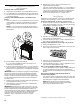
3. Use a ¹⁵⁄₁₆" combination wrench and an adjustable wrench to
attach the flexible connector to the adapters.
IMPORTANT: All connections must be wrench-tightened. Do
not make connections to the gas regulator too tight. Making
the connections too tight may crack the regulator and cause
a gas leak. Do not allow the regulator to turn when tightening
fittings.
Complete Connection
1. Check that the gas pressure regulator shutoff valve is in the
“on” position.
2. Open the manual shutoff valve in the gas supply line. The
valve is open when the handle is parallel to the gas pipe.
3. Test all connections by brushing on an approved
noncorrosive leak-detection solution. If bubbles appear, a
leak is indicated. Correct any leak found.
4. Remove cooktop burner caps and grates from parts
package. Burner caps should be level when properly
positioned. If burner caps are not properly positioned,
surface burners will not light. Place burner grates over
burners and caps.
5. Plug into a grounded 3 prong outlet.
6. Slide range into final location, making sure the rear leveling
leg slides into the slot of the anti-tip bracket.
A. Gas pressure regulator
B. Use pipe-joint compound.
C. Adapter (must have ½" male
pipe thread)
D. Flexible connector
E. Manual gas shutoff valve
F. ½" or ¾" gas pipe
G. Use pipe-joint compound.
H. Adapter
A. Gas pressure regulator shutoff valve
shown in the “on” position
A. Closed valve
B. Open valve
A
B
C
D
E
FG
H
A
A
B
A. Burner base
B. Burner cap
C. Burner grate
C
A
B
Electrical Shock Hazard
Plug into a grounded 3 prong outlet.
Do not remove ground prong.
Do not use an adapter.
Do not use an extension cord.
Failure to follow these instructions can result in death,
fire, or electrical shock.
WARNING