
Technical Manual


FOR SERVICE TECHNICIAN’S USE ONLY
DO NOT REMOVE OR DESTROY2
GENERAL INFORMATION ...............................................................3-8
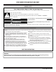
Washer Safety ............................................................................................4
Product Specifications............................................................................ 5-6
Maytag
®
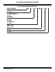
Model Number Nomenclature .......................................................7
Model Number and Serial Number Label Location .......................................8
Tech sheet Location ...................................................................................8
Service Guide ..................................................................................... 9-18
Service Guide...........................................................................................10
Activating Service Mode ...........................................................................10
Reading Binary codes ..............................................................................11
Button Activation & Encoder Test ..............................................................12
Service Test Mode ....................................................................................12
Service Test Mode Chart/Component Activation ........................................13
Software Version Display..........................................................................14
Diagnostic Cycle Chart .............................................................................15
Faults & Error Codes ..........................................................................16–18
Contents
Troubleshooting ................................................................................ 19-28
Troubleshooting Guide ........................................................................ 20–22
Main Control (ACU) Board Connectors and Pinouts ...................................23
Troubleshooting Tests.........................................................................24–28
Component Locations ..............................................................................28
Component Access ........................................................................... 29-40
Removing the Console .............................................................................30
Removing the User Interface (UI) ..............................................................31
Removing the Water Inlet Valve .................................................................32
Removing the Main Control ......................................................................32
Removing the Bulk Dispenser ...................................................................33
Removing the Tub Ring, Impeller, and Basket ............................................34
Removing the Lid Lock .............................................................................37
Removing the Lid and Hinge .....................................................................38
Removing the Shifter ................................................................................39
Removing the Drain Pump ........................................................................40
Removing the Drive Belt and Motor ...........................................................40
Removing the Splutch ..............................................................................41
Removing the Gearcase ...........................................................................42