ELECTRIC DRYER USE & CARE GUIDE SÉCHEUSE ÉLECTRIQUE GUIDE D’UTILISATION ET D’ENTRETIEN FOR QUESTIONS ABOUT FEATURES, OPERATION/PERFORMANCE, PARTS, ACCESSORIES OR SERVICE CALL: 1.800.688.9900 IN CANADA, CALL: 1.800.807.6777 AU CANADA, POUR ASSISTANCE, INSTALLATION OU SERVICE, COMPOSEZ LE : 1.800.807.6777 VISIT OUR WEBSITE AT WWW.MAYTAG.COM IN CANADA, WWW.MAYTAG.CA OU VISITEZ NOTRE SITE INTERNET WWW.MAYTAG.
TABLE OF CONTENTS DRYER SAFETY.......................................................................................................................... 3 INSTALLATION INSTRUCTIONS ............................................................................................. 4 Tools and Parts....................................................................................................................... 4 Location Requirements ............................................................................
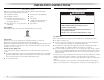
DRYER SAFETY Your safety and the safety of others are very important. We have provided many important safety messages in this manual and on your appliance. Always read and obey all safety messages. This is the safety alert symbol. This symbol alerts you to potential hazards that can kill or hurt you and others. All safety messages will follow the safety alert symbol and either the word “DANGER” or “WARNING.
INSTALLATION INSTRUCTIONS Tools and Parts Location Requirements Gather the required tools and parts before starting installation. Read and follow the instructions provided with any tools listed here. ■ Flat-blade screwdriver ■ Tin snips (new vent installations) ■ #2 Phillips screwdriver ■ Level ■ Adjustable wrench that opens to 1" (2.
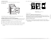
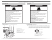
Installation Clearances ■ Companion appliance spacing should also be considered. The location must be large enough to allow the dryer door to open fully. Dryer Dimensions 14" max.* (35.6cm) 18"* (45.7 cm) 22 ³⁄₄" (57.8 cm) 3"* (7.6 cm) 2 48 in. * (310 cm2 ) 24 in. * 2 (155 cm ) 2 43 ³⁄₈" (110 cm) 1" (2.5 cm) 29" (73.66 cm) A 3"* (7.6 cm) 5"* 27¾" 1" 1"* (2.5 cm) (2.5 cm) (70.5 cm) (12.7 cm) B C A. Recessed area B. Side view - closet or confined area C. Closet door with vents *27³⁄₄" (70.
Electrical Requirements - U.S.A. Only It is your responsibility ■ To contact a qualified electrical installer. ■ To be sure that the electrical connection is adequate and in conformance with the National Electrical Code, ANSI/NFPA 70-latest edition and all local codes and ordinances. The National Electric Code requires a 4-wire power supply connection for homes built after 1996, dryer circuits involved in remodeling after 1996, and all mobile home installations.
■ To supply the required 4 wire, single phase, 120/240 volt, 60 Hz., AC only electrical supply on a separate 30-amp circuit, fused on both sides of the line. A time-delay fuse or circuit breaker is recommended. Connect to an individual branch circuit. ■ This dryer is equipped with a CSA International Certified Power Cord intended to be plugged into a standard 14-30R wall receptacle. The cord is 5 ft (1.52 m) in length. Be sure wall receptacle is within reach of dryer’s final location.
Electrical Connection - U.S.A. Only Power Supply Cord Direct Wire WARNING Fire Hazard Fire Hazard Use a new UL listed 30 amp power supply cord. Use 10 gauge solid copper wire. Use a UL listed strain relief. Use a UL listed strain relief. Disconnect power before making electrical connections. Disconnect power before making electrical connections. Connect neutral wire (white or center wire) to center terminal (silver). Connect neutral wire (white or center wire) to center terminal (silver).
■ Put power supply cord through the strain relief. Be sure that the wire insulation on the power supply cord is inside the strain relief. The strain relief should have a tight fit with the dryer cabinet and be in a horizontal position. Do not further tighten strain relief screws at this point. Style 2: Direct wire strain relief ■ Unscrew the removable conduit connector and any screws from a ³⁄₄" (1.9 cm) UL listed strain relief (UL marking on strain relief).
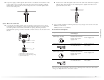
3. Connect ground wire (green or bare) of power supply cord to external ground conductor screw. Tighten screw. 4-wire connection: Power Supply Cord A IMPORTANT: A 4-wire connection is required for mobile homes and where local codes do not permit the use of 3-wire connections. B C F B A C D G E A. 4-wire receptacle (NEMA type 14-30R) B. 4-prong plug C. Ground prong D. Neutral prong E. Spade terminals with upturned ends F. ¾" (1.9 cm) UL listed strain relief G. Ring terminals 1.
4-wire connection: Direct Wire IMPORTANT: A 4-wire connection is required for mobile homes and where local codes do not permit the use of 3-wire connections. Direct wire cable must have 5 ft (1.52 m) of extra length so dryer can be moved if needed. Strip 5" (12.7 cm) of outer covering from end of cable, leaving bare ground wire at 5" (12.7 cm). Cut 1¹⁄₂" (3.8 cm) from 3 remaining wires. Strip insulation back 1" (2.5 cm). Shape ends of wires into a hook shape. 2.
3. Connect ground wire (green or bare) of power supply cable to external ground conductor screw. Tighten screw. A B 3-wire connection: Power Supply Cord Use where local codes permit connecting cabinet-ground conductor to neutral wire: B C E D A C F E D A. External ground conductor screw B. Center silver-colored terminal block screw C. Neutral wire (white or center wire) D. ¾" (1.9 cm) UL listed strain relief E. Ground wire (green or bare) of power supply cable F. Neutral ground wire G F A.
2. Place the hooked end of the neutral wire (white or center wire) of power supply cable under the center screw of terminal block (hook facing right). Squeeze hooked end together. Tighten screw. 3-wire connection: Direct Wire Use where local codes permit connecting cabinet-ground conductor to neutral wire. Direct wire cable must have 5 ft (1.52 m) of extra length so dryer can be moved if needed. Strip 3¹⁄₂" (8.9 cm) of outer covering from end of cable. Strip insulation back 1" (2.5 cm).
3. Connect the other wires to outer terminal block screws. Tighten screws. Optional 3-wire connection Use for direct wire or power supply cord where local codes do not permit connecting cabinet-ground conductor to neutral wire. 1. Remove center silver-colored terminal block screw. 2. Remove neutral ground wire from external ground conductor screw. Connect neutral ground wire and the neutral wire (white or center wire) of power supply cord/cable under center, silver-colored terminal block screw.
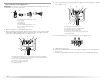
■ If this is a new vent system Exhaust vent must not be connected or secured with screws or other fastening devices that extend into the interior of the duct. Do not use duct tape. Vent material ■ Use a heavy metal vent. Do not use plastic or metal foil vent. ■ 4" (10.2 cm) heavy metal exhaust vent and clamps must be used. Clamp Exhaust Recommended hood styles are shown here. 4" 10.2 cm B 4" (10.
Plan Vent System Alternate installations for close clearances Choose your exhaust installation type Venting systems come in many varieties. Select the type best for your installation. Two closeclearance installations are shown. Refer to the manufacturer’s instructions. Recommended exhaust installations Typical installations vent the dryer from the rear of the dryer. Other installations are possible. B C D A E A F G B H A. Dryer B. Elbow C. Wall D. Exhaust hood E. Clamps F.
Install Vent System Determine vent path ■ Select the route that will provide the straightest and most direct path outdoors. ■ Plan the installation to use the fewest number of elbows and turns. ■ When using elbows or making turns, allow as much room as possible. ■ Bend vent gradually to avoid kinking. ■ Use the fewest 90° turns possible.
Connect Vent 1. Using a 4" (10.2 cm) clamp, connect vent to exhaust outlet in dryer. If connecting to existing vent, make sure the vent is clean. The dryer vent must fit over the dryer exhaust outlet and inside the exhaust hood. Check that the vent is secured to exhaust hood with a 4" (10.2 cm) clamp. 2. Move dryer into its final location. Do not crush or kink vent. 3. (On gas models) Check that there are no kinks in the flexible gas line. 4.
6. Be certain to keep cardboard spacer centered between doors. Reattach outer door panel to inner door panel so handle is on the side where hinges were just removed. 7. Attach door hinges to dryer door so that the larger hole is at the bottom of the hinge. Complete Installation 1. Check that all parts are now installed. If there is an extra part, go back through the steps to see which step was skipped. 2. Check that you have all of your tools. 3. Dispose of/recycle all packaging materials. 4.
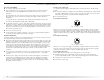
DRYER USE Starting Your Dryer WARNING WARNING Explosion Hazard Fire Hazard Keep flammable materials and vapors, such as gasoline, away from dryer. No washer can completely remove oil. Do not dry anything that has ever had any type of oil on it (including cooking oils). Do not dry anything that has ever had anything flammable on it (even after washing). Items containing foam, rubber, or plastic must be dried on a clothesline or by using an Air Cycle.
Drying Rack Option Use the Drying Rack to dry items such as sweaters and pillows without tumbling. The drum turns, but the rack does not move. If your model does not have a drying rack, you may be able to purchase one for your model. To find out whether your model allows drying rack usage and for information on ordering, please refer to the front page of the manual or contact the dealer from whom you purchased your dryer. NOTE: The rack must be removed for normal tumbling.
As Needed Cleaning For direct-wired dryers: WARNING 1. Roll lint off the screen with your fingers. 2. Wet both sides of lint screen with hot water. 3. Wet a nylon brush with hot water and liquid detergent. Scrub lint screen with the brush to remove residue buildup. 4. Rinse screen with hot water. 5. Thoroughly dry lint screen with a clean towel. Replace screen in dryer. Electrical Shock Hazard Cleaning the Dryer Interior 1.
TROUBLESHOOTING First try the solutions suggested here or visit our website and reference FAQs (Frequently Asked Questions) to possibly avoid the cost of a service call... In U.S.A. www.maytag.com/help - In Canada www.maytag.ca Dryer Operation Dryer will not run ■ Has a household fuse blown, or has a circuit breaker tripped? Electric dryers use 2 household fuses or circuit breakers. The drum may be turning, but you may not have heat. Replace the fuse or reset the circuit breaker.
■ Is the exhaust vent diameter the correct size? Use 4" (10.2 cm) diameter vent material. Cycle time too short WARNING WARNING Excessive Weight Hazard Use two or more people to move and install dryer. Failure to do so can result in back or other injury. Explosion Hazard ■ Keep flammable materials and vapors, such as gasoline, away from dryer. Change the dryness level setting on Automatic Cycles. Increasing or decreasing the dryness level will change the amount of drying time in a cycle.
ASSISTANCE OR SERVICE Before calling for assistance or service, please check “Troubleshooting.” It may save you the cost of a service call. If you still need help, follow the instructions below. When calling, please know the purchase date and the complete model and serial number of your appliance. This information will help us to better respond to your request. If you need replacement parts If you need to order replacement parts, we recommend that you use only factory specified parts.
MAYTAG CORPORATION MAJOR APPLIANCE WARRANTY ONE YEAR LIMITED WARRANTY For one year from the date of purchase, when this major appliance is operated and maintained according to instructions attached to or furnished with the product, Maytag Corporation or Maytag Limited (hereafter “Maytag”) will pay for Factory Specified Parts and repair labor to correct defects in materials or workmanship. Service must be provided by a Maytag designated service company.
SÉCURITÉ DE LA SÉCHEUSE Votre sécurité et celle des autres est très importante. Nous donnons de nombreux messages de sécurité importants dans ce manuel et sur votre appareil ménager. Assurez-vous de toujours lire tous les messages de sécurité et de vous y conformer. Voici le symbole d’alerte de sécurité. Ce symbole d’alerte de sécurité vous signale les dangers potentiels de décès et de blessures graves à vous et à d’autres.
IMPORTANTES INSTRUCTIONS DE SÉCURITÉ AVERTISSEMENT : Pour réduire le risque d'incendie, de choc électrique ou de blessure lors de l'utilisation de la sécheuse, il convient d'observer certaines précautions élémentaires dont les suivantes : ■ ■ ■ ■ ■ ■ ■ ■ Lire toutes les instructions avant d'utiliser la sécheuse. Ne pas placer des articles exposés aux huiles de cuisson dans votre sécheuse.
Les installations pour maison mobile nécessitent un système d’évacuation en métal disponible à l’achat chez le marchand chez qui vous avez acheté votre sécheuse. Pour plus de renseignements, veuillez consulter la section “Assistance ou service”. Dimensions de la sécheuse Exigences d’emplacement 22³⁄₄" (57,8 cm) AVERTISSEMENT 43 ³⁄₈" (110 cm) *27 ³⁄₄" (70,5 cm) Risque d'explosion Garder les matières et les vapeurs inflammables, telle que l’essence, loin de la sécheuse.
Exigences additionnelles concernant l’installation dans une maison mobile Veiller à ce que la prise murale se trouve à proximité de l’emplacement définitif de la sécheuse. Cette sécheuse peut être installée dans une maison mobile.
Exigences concernant l'évacuation AVERTISSEMENT ■ Utiliser un conduit d'évacuation en métal lourd de 4" (10,2 cm) et des brides de serrage. 4" 10,2 cm Conduit d'évacuation en métal lourd de 4" (10,2 cm) Risque d’incendie On peut se procurer les produits d’évacuation auprès du marchand ou en téléphonant à Maytag Services. Pour plus de renseignements, voir la section “Assistance ou service”. Utiliser un conduit d’évacuation en métal lourd. Ne pas utiliser un conduit d’évacuation en plastique.
Le clapet incliné de type boîte ci-dessous est acceptable. Brides de serrage ■ Utiliser des brides pour sceller tous les joints. ■ 4" (10,2 cm) Le conduit d'évacuation ne doit pas être connecté ou fixé avec des vis ou avec tout autre dispositif de serrage qui se prolonge à l'intérieur du conduit. Ne pas utiliser de ruban adhésif pour conduit. 2½" (6,4 cm) ■ Terminer le conduit d'évacuation par un clapet de décharge pour empêcher les rongeurs et insectes d'entrer dans l'habitation.
Autres installations où le dégagement est réduit Il existe de nombreux types de systèmes d’évacuation. Choisir le type qui convient le mieux à l’installation. Deux installations à dégagement réduit sont illustrées. Voir les instructions du fabricant. A Déterminer l'itinéraire d'acheminement du conduit ■ Choisir l'itinéraire d'acheminement vers l'extérieur qui sera le plus direct et le plus rectiligne. ■ Planifier l'installation pour introduire le nombre minimal de coudes et de changements de direction.
Installation du système d’évacuation Raccordement du conduit d’évacuation 1. Installer le clapet d’évacuation. Utiliser du composé de calfeutrage pour sceller l’ouverture murale à l’extérieur autour du clapet d’évacuation. 2. Raccorder le conduit d’évacuation au clapet. Le conduit doit être inséré à l’intérieur du clapet. Fixer ensemble le conduit et le clapet avec une bride de serrage de 4" (10,2 cm). 3. Acheminer le conduit d’évacuation jusqu’à l’emplacement de la sécheuse.
3. Soulever la porte suffisamment pour que les vis supérieures de la caisse se trouvent dans la partie élargie des trous des charnières. Tirer la porte vers l’avant pour la dégager des vis. Placer la porte (poignée vers le haut) sur le dessus de la sécheuse. Ôter les vis supérieures de la caisse. 4. Enlever les vis qui fixent les charnières sur la porte. 5. Enlever les vis au sommet, en bas et sur le côté de la porte (4 vis).
UTILISATION DE LA SÉCHEUSE Mise en marche de la sécheuse AVERTISSEMENT AVERTISSEMENT Risque d'explosion Risque d’incendie Garder les matières et les vapeurs inflammables, telle que l’essence, loin de la sécheuse. Aucune laveuse ne peut complètement enlever l’huile. Ne pas faire sécher des articles qui ont été salis par tout genre d’huile (y compris les huiles de cuisson). Ne pas faire sécher un article qui a déjà été touché par un produit inflammable (même après un lavage).
Fonctionnement du programme de séchage automatique Lors de l'utilisation du programme Auto Moisture Sensing (détection automatique de l'humidité), le degré de séchage de la charge est déterminé par deux bandes métalliques (capteurs) situées à l'intérieur de la sécheuse. Les bandes métalliques aident à “sentir” la quantité d'humidité restant dans les vêtements au moment de leur passage. S'il reste de l'humidité dans les vêtements, le bouton de commande de programme n'avance pas.
ENTRETIEN DE LA SÉCHEUSE Nettoyage de l'emplacement de la sécheuse Éviter de laisser des éléments qui pourraient obstruer le débit de combustion et empêcher une bonne ventilation autour de la sécheuse. AVERTISSEMENT Risque d'explosion Garder les matières et les vapeurs inflammables, telle que l’essence, loin de la sécheuse. Placer la sécheuse au moins 46 cm (18 po) au-dessus du plancher pour une installation dans un garage.
Précautions à prendre pour les vacances et avant un déménagement Période de vacances Changement de l’ampoule du tambour 1. Débrancher la sécheuse ou déconnecter la source de courant électrique. 2. Ouvrir la porte de la sécheuse. Trouver le couvercle de l’ampoule d’éclairage sur la paroi arrière de la sécheuse. Enlever la vis située dans le coin inférieur droit du couvercle. Enlever le couvercle. On ne doit faire fonctionner la sécheuse que lorsqu’on est présent sur place.
■ ■ Les quatre pieds sont-ils installés et la sécheuse est-elle d'aplomb de l'avant vers l'arrière et transversalement? La sécheuse peut vibrer si elle n'est pas correctement installée. Voir les Instructions d'installation. Les vêtements sont-ils emmêlés ou en boule? Une charge en boule rebondit, ce qui fait vibrer la sécheuse. Séparer les articles de la charge et remettre la sécheuse en marche.
Temps de programme trop court Taches sur la charge ou sur le tambour ■ AVERTISSEMENT Risque du poids excessif Les taches sur le tambour sont dues aux teintures contenues dans les vêtements (les jeans en général). Il n'y aura pas de transfert sur les autres vêtements. Utiliser deux ou plus de personnes pour déplacer et installer la sécheuse. Charges froissées Le non-respect de cette instruction peut causer une blessure au dos ou d’autre blessure.
ASSISTANCE OU SERVICE Avant de faire un appel pour assistance ou service, consulter la section “Dépannage”. Ce guide peut vous faire économiser le coût d’une visite de service. Si vous avez encore besoin d’aide, suivre les instructions ci-dessous. Lors d’un appel, veuillez connaître la date d’achat, le numéro de modèle et le numéro de série au complet de l’appareil. Ces renseignements nous aideront à mieux répondre à votre demande.
GARANTIE DES GROS APPAREILS MÉNAGERS MAYTAG CORPORATION GARANTIE LIMITÉE DE UN AN Pendant un an à compter de la date d'achat, lorsque ce gros appareil ménager est utilisé et entretenu conformément aux instructions jointes à ou fournies avec le produit, Maytag Corporation ou Maytag Limited (ci-après désignées “Maytag”) paiera pour les pièces spécifiées par l'usine et la main-d'oeuvre pour corriger les vices de matériaux ou de fabrication.
W10150608A SP PN W10150609A © 2007 All rights reserved. Tous droits réservés. MAYTAG and the “M” Symbol are registered trademarks of Maytag Limited in Canada. MAYTAG et le symbole “M” sont des marques déposées de Maytag Limited au Canada. All other marks are trademarks of Maytag Corporation or its related companies. Toutes les autres marques sont des marques de commerce de Maytag Corporation ou de ses compagnies affiliées. 8/07 Printed in U.S.A. Imprimé aux É.-U.