
Specifications


CONTROL SYSTEM
F57
F
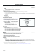
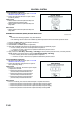
3. Connect the voltmeter test leads to the following
HO2S terminals:
• HO2S (front and rear)
(+) leadterminal A
() leadterminal B
4. With the vehicle stopped, run the engine at 3,000
rpm until the voltmeter moves between 0.5 and
0.7 V.
5. Verify that the measurement voltage changes
when the engine speed increases and decreases
suddenly several times.
• If not as specified, replace the HO2S.
• If the HO2S is okay, but O2S11 or O2S12 PID
value is out of specification, perform the
Circuit Open/Short Inspection.
Specification
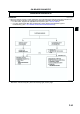
Circuit Open/Short Inspection (Sensor)
1. Disconnect the PCM connector. (See F43 PCM
REMOVAL/INSTALLATION.)
2. Inspect the following wiring harnesses for open or
short. (Continuity check)
Open circuit
• If there is no continuity, the circuit is open. Repair
or replace the harness.
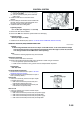
Front
HO2S terminal A (harness-side) and PCM
terminal 1AB (harness-side)
HO2S terminal B (harness-side) and PCM
terminal 2H (harness-side)
Rear
HO2S terminal A (harness-side) and PCM
terminal 1Y (harness-side)
HO2S terminal B (harness-side) and PCM terminal 2H (harness-side)
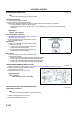
Short circuit
• If there is continuity, the circuit is shorted. Repair or replace the harness.
Front and Rear
HO2S terminal A (harness-side) and body GND
HO2S terminal A (harness-side) and power supply
HO2S terminal B (harness-side) and power supply
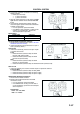
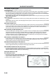
HO2S Heater Resistance Inspection
1. Disconnect the HO2S connector.
2. Measure the resistance between the HO2S
terminals C and D.
• If not as specified, replace the HO2S.
• If the HO2S heater is okay, but PID value is
out of specification, perform the Circuit Open/
Short Inspection.
Specification
Front : 3.03.6 ohms
Rear : 57 ohms
Engine speed Voltage (V)
Acceleration 0.51.0
Deceleration 00.5
A6E3940W017
A6E3940W018
A6E3940W017