
Specifications
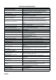
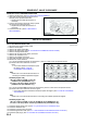

VALVE CLEARANCE
B5
B
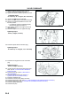
16. Install the splash shield (RH).
17. Install the tire (RH).
End Of Sie
VALVE CLEARANCE ADJUSTMENT
A6E221212111W02
1. Disconnect the negative battery cable.
2. Remove the tire (RH).
3. Remove the splash shield (RH).
4. Remove the spark plugs. (See G10 SPARK PLUG REMOVAL/INSTALLATION.)
5. Remove the high-tension lead.
6. Remove the oil control valve (OCV) connector.
7. Remove the ventilation hose.
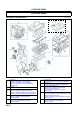
8. Remove the cylinder head cover.
9. Remove the drive belt. (See B3 DRIVE BELT REPLACEMENT.)
10. Remove the joint shaft from the front drive shaft (RH). (See M17 DRIVE SHAFT REMOVAL/INSTALLATION.)
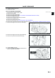
11. Remove the engine front cover lower blind plug.
12. Remove the engine front cover upper blind plug.
13. Remove the cylinder block lower blind plug.
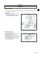
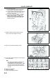
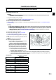
14. Install the SST as shown.
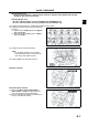
15. Turn the crankshaft clockwise the crankshaft is in
the No.1 cylinder TDC position.
AME2212W002
AME2212W003
AME2212W004