
Specifications
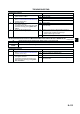

FRONT AXLE
M5
M
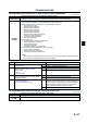
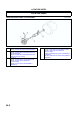
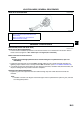
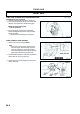
WHEEL HUB, STEERING KNUCKLE REMOVAL/INSTALLATION
A6E631204000W02
Caution
•
••
• Performing the following procedures without first removing the ABS wheel-speed sensor may
possibly cause an open circuit in the harness if it is pulled by mistake. Before performing the
following procedures, remove the ABS wheel-speed sensor (axle side) and fix it to an appropriate
place where the sensor will not be pulled by mistake while the vehicle is being serviced.
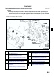
1. Remove in the order indicated in the table.
2. Install in the reverse order of removal.
3. After installation, inspect the front wheel alignment. (See R5 FRONT WHEEL ALIGNMENT.)
.
A6E0612W075
1 Locknut
(See M6 Locknut Removal Note)
(See M9 Locknut Installation Note)
2 Brake caliper component
3 Disc plate
(See P20 Disc Plate Removal Note)
4 Tie-rod end ball joint
(See N11 Tie-rod End Ball Joint Removal Note)
5Bolt
6 Front lower arm (front) ball joint
(See R16 Front Lower Arm (Front) Ball Joint
Removal Note)
7 Front lower arm (rear) ball joint
(See R19 Front Lower Arm (Rear) Ball Joint
Removal Note)
8 Front upper arm ball joint
(See R13 Front Upper Arm Ball Joint Removal
Note)
9 Wheel hub, steering knuckle, dust cover
10 Wheel hub component
(See M6 Wheel Hub Component Removal Note)
(See M8 Wheel Hub Component Installation Note)
11 Retaining ring
12 Wheel bearing
(See M6 Wheel Bearing Removal Note)
(See M8 Wheel Bearing Installation Note)
13 Dust cover
(See M7 Dust Cover Removal Note)
(See M8 Dust Cover Installation Note)
14 Steering knuckle
15 Hub bolt
(See M7 Hub Bolt Removal Note)
(See M7 Hub Bolt Installation Note)