
Specifications


DRIVE SHAFT
M23
M
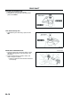
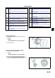
4. Release any trapped air from the boots by
carefully lifting up the small end of each boot with
a cloth wrapped screwdriver.
Caution
•
••
• Do not let grease leak.
•
••
• Do not damage the boot.
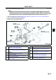
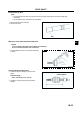
5. Verify that the drive shaft length is within the
standard.
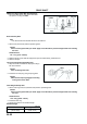
Boot Band (Transaxle Side) Assembly Note
1. Fold the band in the direction opposite to the
forward revolving direction of the drive shaft and
use pliers to pull it tight.
2. Lock the end of the band by bending the locking
clips.
Caution
•
••
• Install the band into the groove securely.
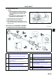
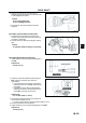
Boot Band (Wheel Side) Assembly Note
1. Adjust clearance A by turning the adjusting bolt of
the SST.
Clearance A
2.9 mm {0.11 in}
2. Crimp the wheel side small boot band using the
SST. Verify that clearance B is within the
specification.
• If clearance B is more than the specification,
reduce clearance A of the SST and crimp the
boot again.
• If clearance B is less than the specification,
replace the boot band, increase clearance A
of the SST, and crimp the new boot.
Clearance B
2.42.8 mm {0.0950.110 in}
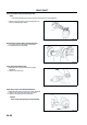
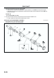
3. Verify that the boot band does not protrude from
the boot band installation area.
• If it does, replace the boot band and repeat Steps 2 and 3.
4. Fill the boot with the repair kit grease.
5. Adjust clearance A by turning the adjusting bolt of the SST.
Clearance A
3.2 mm {0.13 in}
A6E6316W007
A6E6316W008
A6E0350W012
A6E0350W013