Table of Contents Introduction Congratulations Safety and environment protection Symbol glossary Instrument Cluster 4 4 5 8 14 Warning and control lights Gauges 14 19 Entertainment Systems 23 AM/FM AM/FM AM/FM AM/FM stereo stereo with single CD stereo with CD stereo cassette with single CD Climate Controls Heater only Manual heating and air conditioning Lights Headlamps Bulb replacement Driver Controls Steering wheel adjustment Power windows 23 27 34 48 72 72 74 77 77 79 86 87 89 Locks and
Table of Contents Seating and Safety Restraints Seating Safety restraints Air bags Child restraints Driving 111 113 125 135 147 Starting Brakes Transmission operation Vehicle loading Trailer towing Recreational towing 147 152 157 169 171 178 Roadside Emergencies 180 Hazard flasher switch Fuses and relays Changing tires Jump starting Wrecker towing 181 183 194 201 206 Customer Assistance 207 Reporting safety defects (U.S.
Table of Contents Maintenance and Specifications Hood Engine compartment Engine oil Battery Fuel information Refill capacities Lubricant specifications Engine data Vehicle dimensions 224 233 234 238 244 251 273 276 277 277 Accessories 280 Index 281 All rights reserved.
Introduction The following warning may be required by California law: CALIFORNIA Proposition 65 Warning WARNING: Engine exhaust, some of its constituents, and certain vehicle components contain or emit chemicals known to the State of California to cause cancer and birth defects or other reproductive harm.
Introduction WARNING: In the event of an accident the Fuel pump shut-off switch will automatically cut off the fuel supply to the engine. The switch can also be activated through sudden vibration (e.g. collision when parking). To reset the switch, refer to the Fuel pump shut-off switch in the Roadside emergencies chapter.
Introduction SPECIAL NOTICES Emission warranty The New Vehicle Limited Warranty includes Bumper to Bumper Coverage, Safety Restraint Coverage and Corrosion Coverage. In addition, your vehicle is eligible for Emissions Defect and Emissions Performance Warranties. For a detailed description of what is covered and what is not covered, refer to the Warranty Guide that is provided to you along with your Owner’s Guide.
Introduction Notice to owners of pickup trucks and utility type vehicles WARNING: Utility vehicles have a significantly higher rollover rate than other types of vehicles. Before you drive your vehicle, please read this Owner’s Guide carefully. Your vehicle is not a passenger car. As with other vehicles of this type, failure to operate this vehicle correctly may result in loss of control or an accident. Using your vehicle with a snowplow WARNING: Do not use this vehicle for snowplowing.
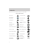
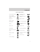
Introduction These are some of the symbols you may see on your vehicle.
Introduction Vehicle Symbol Glossary Power Window Lockout Child Safety Door Lock/Unlock Interior Luggage Compartment Release Symbol Panic Alarm System Feature Engine Oil Engine Coolant Engine Coolant Temperature Do Not Open When Hot Battery Avoid Smoking, Flames, or Sparks Battery Acid Explosive Gas Fan Warning Power Steering Fluid Maintain Correct Fluid Level MAX MIN Emission System Engine Air Filter Passenger Compartment Air Filter Jack Check fuel cap Low tire warning 9
Introduction INFORMATION ABOUT THIS GUIDE The information found in this guide was accurate at the time of printing. Mazda may change the contents without notice.
Instrument Cluster 11
Instrument Cluster Instrument panel dimmer control (pg. 78) Instrument cluster (pg. 14) Headlamp control (pg. 77) DOOR AJAR CHECK GAGE 4 3 H CHECK ENGINE 5 6 30 20 1 CHECK FUEL CAP F ABS 10 0 ! E 60 70 80 0 0 0 80 100 P 40 90 120 60 2 C 50 40 RPMx1000 140 000000 20 MPH R N D 2 1 160 100 180 110 km/h 120 H SPEED CONT L 4WD HIGH H 4WD LOW L THEFT BRAKE O/D OFF OFF DIM ON SET ACC OFF Turn signal and wiper/washer control (pg. 79) COAST Speed control* (pg.
Instrument Cluster Audio system (pg. 23) 4wd control* (pg. 164) 2WD 4X4 HIGH Auxiliary power point (pg. 88) VOL PUSH ON 4X4 LOW TONE TONE VOL ST SEEK DX FM 12 TUNE CLK 1 2 3 4 AM/FM OFF ON OFF OFF PASSENGER AIRBAG Fog lamp control (pg. 77) Passenger air bag deactivate switch (pg. 130) Climate control system (pg.
Instrument Cluster WARNING LIGHTS AND CHIMES Warning lights and gauges can alert you to a vehicle condition that may become serious enough to cause expensive repairs. A warning light may illuminate when a problem exists with one of your vehicle’s functions. Many lights will illuminate when you start your vehicle to make sure the bulb works. If any light remains on after starting the vehicle, have the respective system inspected immediately.
Instrument Cluster without these or any other temporary malfunctions present, the light should turn off. (A driving cycle consists of a cold engine startup followed by mixed city/highway driving.) No additional vehicle service is required. If the light remains on, have your vehicle serviced at the first available opportunity. CHECK NOTE: The ENGINE light will illuminate if vehicle refueling is conducted with the engine running. WARNING: Never refuel vehicle with the engine running.
Instrument Cluster warning light does not illuminate as described, seek service immediately. Illumination after the parking brake is released indicates low brake fluid level or a brake system malfunction and the brake system should be serviced immediately by a qualified technician. Refer to Brakes in the Driving chapter for more information. WARNING: Illumination after releasing the parking brake indicates low brake fluid level and the brake system should be inspected immediately.
Instrument Cluster Charging system Illuminates when the battery is not charging properly. Check fuel cap Illuminates when the fuel cap is not CHECK installed correctly. Check the fuel FUEL cap for proper installation. When CAP the fuel filler cap is properly re-installed, the light(s) will turn off after a period of normal driving. Continuing to operate the vehicle with the check fuel cap light on, can activate the Check Engine warning light.
Instrument Cluster Turn signals Illuminates when the turn signals or the hazard lights are turned on. If the lights stay on continuously or flash faster, check for a burned-out bulb. High beams Illuminates when the high beam headlamps are turned on. Door ajar Illuminates when any door is open (or not fully closed). DOOR AJAR Anti-theft system (if equipped) Refer to SecuriLocky passive anti-theft system in the Locks and Security chapter.
Instrument Cluster Safety belt warning chime Sounds to remind you to fasten your safety belts. BeltMinder chime Sounds intermittently to remind you to fasten your safety belts. Supplemental restraint system (SRS) warning chime Sounds when a malfunction in the supplemental restraint system (front or side airbags) has been detected. Have the supplemental restraint system inspected immediately.
Instrument Cluster Engine coolant temperature gauge Indicates the temperature of the engine coolant. At normal operating temperature, the needle remains within the normal area (the area between the “H” and “C”). If it enters the red section, the engine is overheating. Stop the vehicle as soon as safely possible, switch off the engine immediately and let the engine cool. Refer to Engine coolant in the Maintenance and specifications chapter.
Instrument Cluster Battery voltage gauge Indicates battery voltage. NOTE: If the pointer moves and stays outside the normal operating range (as indicated by arrows), have the vehicle’s electrical system checked as soon as possible. H L Fuel gauge Displays approximately how much fuel is in the fuel tank. The fuel gauge may vary slightly when the vehicle is in motion or on a grade.
Instrument Cluster Odometer Registers the total kilometers (miles) of the vehicle. Trip odometer Registers the kilometers (miles) of individual journeys. To reset, depress the control. 50 40 60 70 80 0 0 0 80 100 60 30 20 10 Tachometer Indicates the engine speed in revolutions per minute. Driving with your tachometer pointer continuously at the top of the scale may damage the engine.
Entertainment Systems AM/FM STEREO VOL PUSH ON TONE TONE VOL ST SEEK DX FM 12 TUNE CLK 1 2 Volume/power control Press the control to turn the audio system on or off. Turn the control to raise or lower volume. 3 4 AM/FM VOL PUSH ON VOL PUSH ON If the volume is set above a certain level and the ignition is turned off, the volume will come back on at a “nominal” listening level when the ignition switch is turned back on.
Entertainment Systems AM/FM select The AM/FM select control works in radio mode. AM/FM AM/FM select in radio mode This control allows you to select AM or FM frequency bands. Press the control to switch between AM, FM1 or FM2 memory preset stations. Tune adjust The tune control works in radio mode. Tune adjust in radio mode • Press to move to the next SEEK frequency down the band (whether or not a listenable TUNE station is located there). Hold the control to move through the frequencies quickly.
Entertainment Systems Radio station memory preset 1 2 3 4 The radio is equipped with four station memory preset controls. These controls can be used to select up to four preset AM stations and eight FM stations (four in FM1 and four in FM2). Setting memory preset stations 1. Select the frequency band with the AM/FM select control. 2. Select a station. Refer to Tune adjust or Seek function for more information on selecting a station. 3.
Entertainment Systems Speaker balance adjust Speaker sound distribution can be adjusted between the right and left speakers. Press the TONE control three times, then use the volume knob to adjust the desired level. Setting the clock Press CLK to toggle between listening frequencies and clock mode. To set the hour, press and hold the CLK control until CLOCK SET appears in the display and press the SEEK control: • • VOL PUSH ON TONE CLK TONE CLK to decrease hours and to increase hours.
Entertainment Systems • to decrease minutes and to increase minutes. • The CLK control will allow you to switch between media display mode (radio station, stereo information, etc.) and clock display mode (time). When in clock mode, the media information will display for ten seconds, when the radio is turned on, and then revert to clock information. Any time that the media is changed, (new radio station, etc.), the media information will again display for ten seconds before reverting back to the clock.
Entertainment Systems Volume/power control Press the control to turn the audio system on or off. Turn the control to raise or lower volume. VOL - PUSH ON VOL - PUSH ON If the volume is set above a certain level and the ignition is turned off, the volume will come back on at a “nominal” listening level when the ignition switch is turned back on. AM/FM select The AM/FM select control works in radio and CD modes.
Entertainment Systems Tune adjust The tune control works in radio mode. Tune adjust in radio mode • Press to move to the next SEEK frequency down the band TUNE DISCS (whether or not a listenable station is located there). Hold the control to move through the frequencies quickly. to move to the next frequency up the band (whether or not • Press a listenable station is located there). Hold for quick movement. Seek function The seek function control works in radio or CD mode.
Entertainment Systems Scan function in radio mode Press SCN to hear a brief sampling of all listenable stations on the frequency band. Press SCN again to stop the scan mode. Scan function in CD mode Press SCN to hear a short sampling of all selections on the CD. (The CD scans in a forward direction, wrapping back to the first track at the end of the CD.) To stop on a particular selection, press the control again.
Entertainment Systems Treble adjust The treble adjust control allows you to increase or decrease the audio system’s treble output. TREB Speaker balance adjust Speaker sound distribution can be adjusted between the right and left speakers. BAL Speaker fade adjust Speaker sound can be adjusted between the front and rear speakers. FADE CD select • To begin CD play (if CD[s] are loaded), press the CD control. The first track of the disc will begin playing.
Entertainment Systems This player is designed to use standard 4 5⁄8 compact discs. Do not insert any promotional (odd shaped or sized) discs, or discs with removable labels into the CD player as jamming may occur. Rewind The rewind control works in CD mode. To rewind in CD mode press the CD CD control (preset 1). 1 Pressing the control for less than three seconds results in slow rewind. Pressing the control for more than three seconds results in fast rewind.
Entertainment Systems Shuffle feature (if equipped) The shuffle feature operates in CD SHUFFLE mode only and plays all tracks on 6 the current disc in random order. Press the SHUFFLE control to start this feature. Random order play will continue until the SHUFFLE control is pressed again. Setting the clock Press CLK to toggle between listening frequencies and clock mode while in radio mode. To set the hour, press and hold the CLK control. Press the SEEK control: to decrease hours and • to increase hours.
Entertainment Systems MACHT MP3 MUSIC SYSTEM 1. 2. 3. 4. 5. 6. 7. 8. 9. 10. 11. 12. 13. 14.
Entertainment Systems 15. 16. 17. 18. 19. CD fast forward control Shuffle control Compression control Track control Repeat control Volume/power control Press the control to turn the audio system on or off. Turn the control to raise or lower the volume. If the volume is set above a certain level and the ignition is turned off, the volume will come back on at a “nominal” listening level when the ignition switch is turned back on. AM/FM select The AM/FM select control works in radio mode.
Entertainment Systems Tune adjust in radio mode • Press to move to the next frequency down the band. Hold for quick movement through the frequencies. • Press to move to the next frequency up the band. Hold for quick movement through the frequencies. When the top of the band is reached, the tuner will continue to select from the lowest frequency upward. When a radio frequency is in tune, the ST icon will appear in the display for stereo broadcasts.
Entertainment Systems directories containing MP3 files, from 01–01 to 99–99. The first two digits denote the directory number and the last two digits denote the track number wtihin that directory. • Creating discs with only one level of subdirectories will help with navigation through the disc files. Seek function The seek function control works in radio, CD, MP3 flat file mode and MP3 directory modes. Seek function in radio mode • Press to find the next listenable station down the frequency band.
Entertainment Systems Scan function in radio mode Press SCN to engage scan mode and to hear a brief sampling of all listenable stations on the frequency band. When the top of the band is reached, the tuner will continue to scan from the lowest frequency upward. Press SCN again to disengage scan mode. Scan function in CD mode Press SCN to engage scan mode and to hear a brief sampling of all tracks on the disc. The track number in the display will blink while the scan function is enabled.
Entertainment Systems Press SCN to engage scan mode and to hear a brief sampling of all tracks in the current directory. The track number in the display will blink while the scan function is enabled. When the last track is reached, the player will continue to scan from the first track in the current directory forward. Press SCN again to disengage scan mode. To scan tracks in another directory, press or on the TUNE DIR control to select the desired directory.
Entertainment Systems 3. Press and hold a memory preset control until the sound returns, indicating the station is held in memory on the control you selected. Accessing memory preset stations 1. Select the desired frequency band with the AM/FM select control. 2. Press the preset control which contains the desired station frequency. The desired station will begin to play. Bass adjust The bass adjust control allows you to increase or decrease the audio system’s bass output.
Entertainment Systems Speaker balance adjust Speaker sound distribution can be adjusted between the right and left speakers. Speaker fade adjust Speaker sound can be adjusted between the front and rear speakers. CD select The CD select function allows you to play CDs. Playing a CD • If a CD is already loaded, press the CD control. CD play will begin where it stopped last. • If a CD is not already loaded, insert the CD into the system.
Entertainment Systems • Press the MP3 DIR control to engage MP3 directory mode, if desired. The track number format on the display will change from TXXX (XXX=current track number) to XX-XX (directory —track number). Note: If the car’s ignition is turned off and on again, play will begin at the beginning of the last song played. If the radio was powered off by the VOL control, play will start where it last left off. • To stop MP3 disc play, eject the disc or press the AM/FM control.
Entertainment Systems Press and hold the rewind control until the desired selection point is reached. The display will show the elapsed time for each track as you reverse through it. When the beginning of the disc is reached, the first track on the disc will begin to play. Release the rewind control again to disengage rewind mode. Fast forward The fast forward control works in CD mode. It is not enabled in MP3 flat file mode or MP3 directory mode.
Entertainment Systems Shuffle feature in CD mode The shuffle feature plays all tracks on the current disc in random order. • Press the SHUFFLE control to engage random play. SHF and then ON will briefly appear in the display. The player will then begin random play. • To select another random track on the disc, press or on the SEEK control. • Press the SCN control to scan through random tracks. The track number will flash in the display. The shuffle feature will remain enabled.
Entertainment Systems • Press SCN to scan through random tracks. The track number will flash in the display. The shuffle function will remain enabled. • Press SHUFFLE again to disengage the shuffle feature. SHF and then OFF will briefly display and the current track will continue to play. Shuffle feature in MP3 directory mode The shuffle feature in MP3 directory mode allows you to play all the tracks in the current directory in random order.
Entertainment Systems MACHT Track function The MACHt track function allows you to quickly search through a large number of tracks or directories on the MP3 disc. The function works in MP3 flat file mode and MP3 directory mode. Track function in MP3 flat file mode and MP3 directory mode • Press the TRACK control. TRAC will appear in the display. • Rotate the volume control to advance or reverse through the tracks. The MP3 icon will blink in the display while the MACHt track function is enabled.
Entertainment Systems • DISC ERR when there is a damaged or unreadable disc. Such as, data discs containing no .mp3 files, or for data discs containing more than 255 files or directories. • CD ERR for any other disc malfunction. Setting the clock To set the hour, press and hold the CLK control while performing the following functions: • Press on the SEEK control to decrease the hours. on the SEEK control to • Press increase the hours.
Entertainment Systems • When burning a disc, ensure that you close/finalize the disc before playback, or the disc may not play properly or an error message may appear. • The player supports DAM (Digital Automatic Music) discs. PREMIUM AM/FM STEREO/CASSETTE/SINGLE CD DISC VOL PUSH ON EJ FM 1 AMC BL AM ST MUTE RF FM EJ DOLBY B NR TAPE CD AUTO SEEK TUNE SCAN BASS TREB REW FF SIDE 1-2 1 2 3 Volume/power control Press the control to turn the audio system on or off.
Entertainment Systems If the volume is set above a certain level and the ignition is turned off, the volume will come back on at a “nominal” listening level when the ignition switch is turned back on. AM/FM select The AM/FM select control works in radio, tape and CD modes. AM FM AM/FM select in radio mode This control allows you to select AM or FM frequency bands. Press the control to switch between AM, FM1 or FM2 memory preset stations.
Entertainment Systems Seek function in tape mode • Press to listen to the previous selection on the tape. to listen to the next selection on the tape. • Press Seek function in CD mode • Press to seek to the previous track of the disc. • Press to seek forward to the next track of the current disc. After the last track has been completed, the first track of the current disc will automatically replay. Scan function The scan function works in radio, tape or CD mode.
Entertainment Systems Setting memory preset stations 1. Select the frequency band with AM FM the AM/FM select control. 2. Select a station. Refer to Tune adjust or Seek function for more information on selecting a station. 3. Press and hold a memory preset control until the sound returns, indicating the station is held in memory on the control you selected.
Entertainment Systems Bass adjust The bass adjust control allows you to increase or decrease the audio system’s bass output. Press the BASS control then press: to decrease the bass output • and to increase the bass output. • Treble adjust The treble adjust control allows you to increase or decrease the audio system’s treble output. Press the TREB control then press: to decrease the treble output • and • to increase the treble output.
Entertainment Systems Press the BAL control then press: to shift sound to the left and • to shift sound to the right. • Speaker fade adjust Speaker sound can be adjusted between the front and rear speakers. Press the FADE control then press: to shift the sound to the • front and • to shift the sound to the rear. SEL BAL FADE SEL Tape select • To begin tape play (with a tape loaded into the audio system) TAPE CD while in the radio or CD mode, press the TAPE control.
Entertainment Systems • In CD mode, pressing the REW control rewinds the CD within the current track. Fast forward The fast forward control works in FF tape and CD modes. 2 • In the tape mode, tape direction will automatically reverse when the end of the tape is reached. • In CD mode, pressing the control fast forwards the CD within the current track. Tape direction select Press SIDE 1–2 to play the alternate side of a tape. SIDE 1-2 3 Eject function Press the EJ control to stop and eject a tape or CD.
Entertainment Systems Compression adjust Compression adjust brings soft and loud CD passages together for a more consistent listening level. Press the COMP control to activate and deactivate compression adjust. COMP 5 Shuffle feature (if equipped) The shuffle feature operates in CD SHUFFLE mode and plays all tracks on the 6 current disc in random order. Press the SHUFFLE control to start this feature. Random order play will continue until the SHUFFLE control is pressed again.
Entertainment Systems • to decrease minutes and to increase minutes. • If your vehicle has a separate clock, (other than the digital radio display), the CLK control will not function in the above manner. The CLK control will allow you to switch between media display mode AUTO (radio station, stereo information, etc.) and clock display mode (time). When in clock mode, the media information will display for 10 CLK seconds, when the radio is turned on, and then revert to clock information.
Entertainment Systems PREMIUM AM/FM STEREO IN DASH SIX CD RADIO SHUF DISC TUNE SCAN SEEK REW FF COMP MUTE EJ LOAD BASS BAL SEL TREB FADE PUSH ON AM FM CD 1 2 3 4 5 6 MENU Volume/power control Press the control to turn the audio system on or off. PUSH ON Turn the control to raise or lower volume. If the volume is set above a certain level and the ignition is turned off, the volume will come back on at a “nominal” listening level when the ignition switch is turned back on.
Entertainment Systems AM/FM select The AM/FM select control works in radio and CD modes. AM FM CD AM/FM select in radio mode This control allows you to select AM or FM frequency bands. Press the control to switch between AM, FM1 or FM2 memory preset stations. AM/FM select in CD mode Press this control to stop CD play and begin radio play. Tune adjust The tune control works in radio or CD mode.
Entertainment Systems Seek function The seek function works in radio or CD mode. Seek function in radio mode • Press to find the next listenable station down the frequency band. SEEK DOWN will display. • Press to find the next listenable station up the frequency band. SEEK UP will display. Seek function in CD mode • Press to seek to the previous track of the current disc. If the beginning of the disc is reached, the CD player seeks to the beginning of the last track on the current disc and begins playing.
Entertainment Systems Autostore Autostore allows you to set the strongest local radio stations without losing your original manually set preset stations. This feature is helpful on trips when you travel between cities with different radio stations. Starting autostore 1. Press and momentarily hold the AM/FM control. 2. AUTOSET will flash in the AM CD display as the frequency band is FM scrolled through. 3.
Entertainment Systems 4. Press and hold a memory preset control. The playing media will mute momentarily. When the sound returns, the station is held in memory on the control you selected. The display will read SAVED. CD select CD mode may be entered by pressing the CD control and the LOAD control. Load the CD into the audio system. The first track of the disc will begin playing. After that, CD play will begin where it stopped last.
Entertainment Systems This six disc CD player is equipped with a CD door. Compact discs should only be inserted into the player after the door has been opened by the player. Do not attempt to force the door open. Compact discs should only be loaded by pressing the LOAD control. Press the LOAD control. (You can choose which slot will be loaded by pressing the desired preset number. If you do not choose a slot, the system will choose the next available one.) Wait until the CD door opens.
Entertainment Systems Auto eject Press and momentarily hold the EJ control to engage auto eject. All CDs which are present in the player will be ejected one at a time. If a CD is ejected and not removed from the door of the CD player, the player will automatically reload the CD. This feature may be used when the ignition is ON or OFF. Rewind The rewind control works in CD modes. Press and hold the REW control until the desired selection is reached.
Entertainment Systems SHUFFLE TRK plays all the tracks on the current disc in random order. Compression feature The compression feature operates in CD mode and brings soft and loud CD passages together for a more consistent listening level. Press the COMP control until COMP ON is displayed. Bass adjust The bass adjust control allows you to increase or decrease the audio system’s bass output. Press the BASS control. Use the SEL control to increase or decrease the amount of bass.
Entertainment Systems Speaker fade adjust Speaker sound can be adjusted between the front and rear speakers. Press the FADE control. Use the SEL control to adjust the sound between the front and rear speakers. BAL + SEL FADE Menu mode The MENU control allows you to access many different features within your audio system. There are three sets of menus available depending upon which mode or feature is activated. While in FM mode, two menus are available.
Entertainment Systems FIND type — Allows you to select your desired FM program type and search for that selection. SHOW — Allows you to select from NAME (displays the name of the radio station), TYPE (displays the RDS program type: rock, jazz, etc.), or NONE (deactivates the RDS display). Traffic announcements This feature allows you to hear traffic announcements. When in this MENU + SEL mode, traffic announcements will interrupt radio and CD play.
Entertainment Systems Radio data system (RDS) feature This feature allows your audio system to receive text information MENU + SEL from RDS-equipped FM radio stations. To activate RDS: • When in FM mode, press the MENU control until RDS OFF displays. • Press the SEL control to engage this feature (RDS ON). RDS features: Once the RDS feature is on, press the MENU control to scroll through the following selections: Traffic announcements This feature allows you to hear traffic announcements while in CD mode.
Entertainment Systems use the SEEK or SCAN control to find the desired program type from the following selections: • Classic • Country • Info • Jazz • Oldies • R&B • Religious • Rock • Soft • Top 40 Show This feature allows you to select the type of RDS broadcast information the radio will regularly show in the display. MENU + SEL With RDS activated, press the MENU control until SHOW is MENU + SEL displayed.
Entertainment Systems Use the SEL control to manually set the time. SEL • Press to increase hours/minutes. to decrease • Press hours/minutes. Press the MENU control again to disengage the clock mode. CLEANING COMPACT DISCS Inspect all discs for contamination before playing. If necessary, clean discs only with an approved CD cleaner and wipe from the center out to the edge. Do not use circular motion.
Entertainment Systems CD, MP3 AND CD PLAYER CARE • Handle discs by their edges only. Never touch the playing surface. • Do not expose discs to direct sunlight or heat sources for extended periods of time. • Do not insert more than one disc into the slot of the CD player (if equipped). • Always store discs out of direct sunlight. Excessive heat may damage or warp discs.
Entertainment Systems • Do not leave tapes in the cassette player for a long time when not being played. RADIO FREQUENCY INFORMATION The Federal Communications Commission (FCC) and the Canadian Radio and Telecommunications Commission(CRTC) establish the frequencies AM and FM stations may use for their broadcasts. Allowable frequencies are: AM 530, 540–1600, 1610 kHz FM 87.7, 87.9–107.7, 107.9 MHz Not all frequencies are used in a given area.
Climate Controls HEATER ONLY SYSTEM Fan speed control Controls the volume of air circulated in the vehicle. Temperature control knob Controls the temperature of the airflow inside the vehicle. On heater-only systems, the air cannot be cooled below the outside temperature. Mode selector control Controls the direction of the airflow to the inside of the vehicle. (Panel) – Distributes outside • air through the instrument panel registers. • OFF – Outside air is shut out and the fan will not operate.
Climate Controls • (Defrost) – Distributes outside air through the windshield defroster ducts. It can be used to clear ice or fog from the windshield. Operating tips • In humid weather, place the climate control system in DEF before driving. This will reduce fogging on your windshield. Once the windshield has been cleared, select any desired position. • To reduce humidity buildup inside the vehicle, do not drive with the climate control system in the OFF position.
Climate Controls MANUAL HEATING AND AIR CONDITIONING SYSTEM OFF A/C MAX A/C Fan speed control Controls the volume of air circulated in the vehicle. Temperature control knob Controls the temperature of the airflow inside the vehicle. Mode Selector Control Controls the direction of the airflow to the inside of the vehicle. OFF A/C MAX A/C The air conditioning compressor can operate in all modes except and .
Climate Controls • A/C – Uses outside air to cool the vehicle. It is quieter than MAX A/C but not as economical. Airflow will be from the instrument panel registers. • (Panel) – Distributes outside air through the instrument panel registers. However, the air will not be cooled below the outside temperature because the air conditioning does not operate in this mode. • OFF – Outside air is shut out and the fan will not operate.
Climate Controls • To reduce humidity buildup inside the vehicle in warm weather conditions, don’t drive with the climate control system in the OFF position. • Under normal weather conditions, your vehicle’s climate control system should be left in any position other than the MAX A/C or OFF when the vehicle is parked. This allows the vehicle to “breathe” through the outside air inlet duct.
Lights HEADLAMP CONTROL Rotate the headlamp control to the first position to turn on the parking lamps. Rotate to the second position to turn on the headlamps. OFF FOG LAMP CONTROL (IF EQUIPPED) The fog lamps can only be turned on when the headlamp control is in the low beams position. Press the foglamp control to activate the fog lamps. The fog lamp indicator light will illuminate. When the highbeams are activated, the fog lamps will not operate.
Lights High beams • Push forward past detent to activate. • Pull toward you past detent to deactivate. Flash to pass Pull toward you slightly to activate and release to deactivate. PANEL DIMMER CONTROL Use to adjust the brightness of the instrument panel during headlamp and parklamp operation. • Rotate up to brighten. • Rotate down to dim. • Rotate to full up position (past DIM detent/dome defeat) to turn on interior lamps.
Lights TURN SIGNAL CONTROL • Push down to activate the left turn signal. • Push up to activate the right turn signal. COURTESY/READING LAMPS (IF EQUIPPED) The courtesy lamp lights when: • any door is opened. • the instrument panel dimmer switch is held up until the courtesy lamps come on. • the remote entry controls are pressed and the ignition is OFF. The reading lamps can be turned on by moving the switch on the dome lamp to either the left or the right.
Lights Do not remove lamp bulbs unless they can be replaced immediately with new ones. If a bulb is removed for an extended period of time, contaminants may enter the lamp housings and affect lamp performance. Using the right bulbs Replacement bulbs are specified in the chart below. Headlamp bulbs must be marked with an authorized “D.O.T.” for North America to assure lamp performance, light brightness and pattern and safe visibility.
Lights Replacing headlamp bulbs To remove the headlamp bulb: 1. Make sure headlamp switch is in OFF position, then open the hood. 2. At the back of the headlamp, pry up the two retainer pins to release the headlamp assembly from the vehicle and pull headlamp forward. 3. Remove the bulb retaining ring by rotating it counterclockwise (when viewed from the rear) to free it from the bulb socket, and slide the ring off the plastic base. Keep the ring to retain the new bulb. 4.
Lights 2. Install the bulb retaining ring over the plastic base until it contacts the rear of the socket by rotating clockwise until you feel a “stop.” 3. Install the electrical connector into the plastic base until it snaps, locking it into position. 4. Install the headlamp on vehicle, push rearward and secure with two retainer pins. 5. Turn the headlamps on and make sure they work properly. If the headlamp was correctly aligned before you changed the bulb, you should not need to align it again.
Lights 5. Rotate bulb socket counterclockwise and remove from lamp assembly. 6. Carefully pull bulb straight out of socket and push in the new bulb. 7. Install the bulb socket in lamp assembly by turning clockwise. 8. Align the lamp on the vehicle and push to snap in place. 9. Install screw(s) on lamp assembly. 10. Install the headlamp on vehicle, push rearward and secure with two retainer pins.
Lights 3. Rotate bulb socket counterclockwise turn and remove from lamp assembly. 4. Carefully pull the bulb straight out of the socket and push in the new bulb. 5. Install the bulb socket in lamp assembly by turning clockwise. 6. Install the lamp assembly and secure with four screws. Replacing fog lamp bulbs 1. Remove the bulb socket from the fog lamp by turning counterclockwise. 2. Disconnect the electrical connector from the fog lamp bulb. 3. Connect the electrical connector to the new fog lamp bulb. 4.
Lights To remove the brake lamp assembly: 1. Remove the two screws and lamp assembly from vehicle. 2. Remove the bulb socket from lamp assembly by rotating it counterclockwise. 3. Carefully pull bulb straight out of socket and push in the new bulb. To install the brake lamp assembly: 1. Install the bulb socket into the lamp assembly by rotating clockwise. 2. Install the lamp assembly on the vehicle and secure with two screws.
Driver Controls WINDSHIELD WIPER/WASHER CONTROLS Rotate the windshield wiper control to the desired interval, low or high speed position. The bars of varying length are for intermittent wipers. When in this position rotate the control upward for fast intervals and downward for slow intervals. Push (tap) the end of the stalk briefly for a single swipe (no wash). Push and hold for three swipes with wash. Push and hold for a longer wash (up to ten seconds).
Driver Controls Changing the wiper blades To replace the wiper blades: 1. Pull the wiper arm away from the windshield and lock into the service position. 2. Turn the blade at an angle from the wiper arm. Push the lock pin manually to release the blade and pull the wiper blade down toward the windshield to remove it from the arm. 3. Attach the new wiper to the wiper arm and press it into place until a click is heard.
Driver Controls WARNING: Never adjust the steering wheel when the vehicle is moving. You could lose control of the vehicle. AUXILIARY POWER POINT SEEK 12V TUNE 1 2 3 4 AM-FM OFF A/C MAX A/C Power outlets are designed for accessory plugs only. Do not hang any type of accessory or accessory bracket from the plug. Improper use of the power outlet can cause damage not covered by your warranty. The auxiliary power point is located on the instrument panel.
Driver Controls POWER WINDOWS (IF EQUIPPED) Press and hold the rocker switches to open and close windows. • Press the top portion of the rocker switch to close. AUTO • Press the bottom portion of the rocker switch to open. AUTO One touch down • Press AUTO completely down and release quickly. The driver’s window will open fully. Depress again to stop window operation. One touch down can be deactivated during operation by pushing down on the top part of the driver power window control.
Driver Controls AUTOMATIC DIMMING REAR VIEW MIRRORS (IF EQUIPPED) Your vehicle is equipped with an inside rear view mirror with an auto-dimming function. The electronic day/night mirror will change from the normal state to the non-glare state when bright lights (glare) reach the inside rear view mirror. When the inside rear view mirror detects bright light from behind the vehicle, the inside rear view mirror will automatically adjust (darken) to minimize glare.
Driver Controls OUTSIDE AIR TEMPERATURE Display operation of the mirror with the compass feature: • Press the right button to toggle the display between the compass direction and no display. Display operation of mirror with temperature and compass feature: • Press the right button once to display temperature °F and compass. • Press the right button twice to display temperature °C and compass. • Press the right button three times to turn the display OFF.
Driver Controls 3. To change the zone setting, push and hold the right button until ZONE appears in the display. 4. Press the right button repeatedly until desired compass zone number is displayed. The display will change back to the compass direction after 3 seconds when the button is not activated. COMPASS CALIBRATION ADJUSTMENT The compass calibrates itself under normal driving conditions. There is not a need for manual compass calibration. If calibration is still desired, follow these instructions: 1.
Driver Controls POWER MIRROR CONTROL (IF EQUIPPED) To adjust your mirrors: to adjust the left 1. Select mirror or to adjust the right mirror. 2. Move the control in the direction you wish to tilt the mirror. 3. Return to the center position to lock mirrors in place. SPEED CONTROL (IF EQUIPPED) To turn speed control on • Press ON. NOTE: Vehicle speed cannot be controlled until the vehicle is traveling at or above 48 km/h (30 mph).
Driver Controls To turn speed control off • Press OFF. NOTE: Once speed control is turned off or the ignition is switched off, the previously programmed set speed will be erased. ON OFF To set a speed • Press SET ACC. NOTE: For speed control to operate, the speed control must be ON and the vehicle speed must be greater than 48 km/h (30 mph). RSM SET ACC COAST If you drive up or down a steep hill, your vehicle speed may vary momentarily slower or faster than the set speed. This is normal.
Driver Controls To set a higher set speed • Press and hold SET ACC. Release the control when the desired vehicle speed is reached or RSM • Press and release SET ACC to SET operate the Tap-Up function. ACC Each press will increase the set speed by 1.6 km/h (1 mph) or COAST • Accelerate with your accelerator pedal. When the desired vehicle speed is reached, press and release SET ACC. NOTE: You can accelerate with the accelerator pedal at any time during speed control usage.
Driver Controls To disengage speed control • Depress the brake pedal or • Depress the clutch pedal (if equipped). NOTE: Disengaging the speed control will not erase the previously programmed set speed. NOTE: Fully depressing the clutch pedal may cause a flare in engine RPM as the throttle is returned to idle. This is normal. NOTE: Pressing OFF will erase the previously programmed set speed.
Driver Controls To return to a previously set speed • Press RSM. For RSM to operate, the vehicle speed must be faster than 48 km/h (30 mph). RSM SET ACC COAST Indicator light This light comes on when either the SPEED SET ACCEL or RES controls are pressed. It turns off when the speed CONT control OFF control is pressed, the brake or clutch is applied or the ignition is turned to the OFF position.
Driver Controls To return to normal overdrive mode, press the Transmission Control O/D ON/OFF Switch again. The O/D Off indicator light will no longer be illuminated. When you shut off and re-start your vehicle, the transmission will automatically return to normal (Overdrive) mode. For additional information about the gearshift lever and the transmission control switch operation refer to the Automatic Transmission Operation section of the Driving chapter.
Driver Controls BED EXTENDER (IF EQUIPPED) Your vehicle may be equipped with a bed extender designed to extend the pickup box for longer loads. To extend the bed extender: 1. Lower tailgate. 2. Pull the round knobs on each side of the extender to release it from the pickup box. 3. Pivot extender on to the tailgate.
Driver Controls 4. Evenly push down on the extender and push the round knobs in on each side locking it in place. Green markings on the shaft indicate the locked position. The locking clip screws below the middle bar can be tightened counterclockwise for extra security. To stow the bed extender, follow steps one through four in reverse order. The bed extender may be used to secure a load of up to 46 kg (100 lbs.) on the tailgate.
Driver Controls To remove the bed extender: 1. Extend the bed extender. 2. Pull the round knobs on each side of the extender to unlock it. Make sure the locking clip screws are loose before removing the extender. 1. Press the locking clips below the middle bar on each side and lift the extender out of the bed. To install the bed extender, follow the removal procedure in reverse order.
Locks and Security KEYS The key operates all locks on your vehicle. In case of loss, replacement keys are available from your dealer. You should always carry a second key with you in a safe place in case you require it in an emergency. Refer to SecuriLocky Passive Anti-Theft System for more information. POWER DOOR LOCKS (IF EQUIPPED) Press the top of the control to unlock all doors and the bottom to lock all doors.
Locks and Security Unlocking the doors Press this control to unlock the driver’s door. The interior lamps will illuminate. Press the control a second time within five seconds to unlock all doors. Locking the doors Press this control to lock all doors. To confirm all doors are closed and locked, press the control a second time within five seconds. The doors will lock again, the horn will chirp and the lamps will flash.
Locks and Security Power door lock disable feature This feature will help protect your vehicle from unauthorized entry. The UNLOCK function on the power door switch will not operate with the ignition OFF and twenty seconds after the doors are closed and electronically locked by the key fob, key pad, or power door switch (if pressed while the door was open).
Locks and Security Replacing the battery The transmitter is powered by one coin type three-volt lithium battery CR2032 or equivalent. Typical operating range will allow you to be up to 10 meters (33 feet) away from your vehicle. A decrease in operating range can be caused by: • weather conditions • nearby radio towers • structures around the vehicle • other vehicles parked next to the vehicle To replace the battery: 1. Twist a thin coin between the two halves of the transmitter near the key ring.
Locks and Security Programming remote transmitters It is necessary to have all (maximum of four — original and/or new) of your remote transmitters available prior to beginning this procedure. NOTE: This procedure must be completed within the specified times. If not completed within the specified time period, reprograming procedures must be restarted from the beginning.
Locks and Security Automatic arming The vehicle is armed immediately after switching the ignition to the 3 (OFF) position. The THEFT light in the instrument cluster will flash every two seconds when the vehicle is armed. 4 3 5 2 1 Automatic disarming Switching the ignition to the 4 (ON) position with a coded key disarms the vehicle. The THEFT light will illuminate for three seconds and then go out.
Locks and Security The SecuriLocky passive anti-theft system is not compatible with aftermarket remote start systems. Use of these systems may result in vehicle starting problems and a loss of security protection. NOTE: Large metallic objects, electronic devices on the key chain that can be used to purchase gasoline or similar items, or a second key on the same key ring as the coded key may cause vehicle starting issues.
Locks and Security If your keys are lost or stolen you will need to do the following: • Use your spare key to start the vehicle. or • Have your vehicle towed to an authorized Mazda dealership. . The key codes will need to be erased from your vehicle and new key codes will need to be re-coded. Replacing coded key can be very costly and you may want to store an extra programmed key away from the vehicle in a safe place to prevent an unforeseen inconvenience.
Locks and Security 1. Insert the first previously programmed coded key into 4 the ignition and turn the 3 ignition from 3 (OFF) to 4 (ON) 5 (maintain ignition in 4 (ON) for at least one second). 2 2. Turn ignition to 3 (OFF) then 2 (LOCK) and remove the first coded key from the ignition. 1 3.
Seating and Safety Restraints SEATING Adjusting the front manual seat WARNING: Never adjust the driver’s seat or seatback when the vehicle is moving. Sudden braking or a collision could cause serious injury. Adjust the seat only when the vehicle is stopped. WARNING: Do not pile cargo higher than the seatbacks to reduce the risk of injuring people in a collision or sudden stop. WARNING: Always drive and ride with your seatback upright and the lap belt snug and low across the hips.
Seating and Safety Restraints Pull lever up to adjust seatback. Using the manual lumbar support (if equipped) Turn the lumbar support control clockwise to increase firmness. Turn the lumbar support control counterclockwise to increase softness. REAR SEATS Center facing jump seat (2 door SuperCab) (if equipped) To open, pull inboard and down on the seat handle. To stow the seat, pull seat bottom back to the fully upright position. WARNING: Do not install a child seat in a center facing jump seat.
Seating and Safety Restraints Center facing jump seat (4 door CabPlus) (if equipped) To open, pull seat assembly down, then raise seatback. To stow the seat, fold seat back down and raise seat assembly to the fully upright position. WARNING: Do not install a child seat in a center facing jump seat. SAFETY RESTRAINTS Safety restraints precautions WARNING: Always drive and ride with your seatback upright and the lap belt snug and low across the hips.
Seating and Safety Restraints WARNING: In a rollover crash, an unbelted person is significantly more likely to die or be seriously injured than a person wearing a seat belt. WARNING: In a rollover crash, an unbelted person is significantly more likely to die than a person wearing a safety belt. WARNING: Each seating position in your vehicle has a specific safety belt assembly which is made up of one buckle and one tongue that are designed to be used as a pair.
Seating and Safety Restraints 2. To unfasten, push the release button and remove the tongue from the buckle. The front outboard safety restraints in the vehicle are combination lap and shoulder belts. The front passenger outboard safety belt has two types of locking modes described below: Energy Management Feature • This vehicle has a seat belt system with an energy management feature at the front outboard seating positions to help further reduce the risk of injury in the event of a head-on collision.
Seating and Safety Restraints How to use the automatic locking mode • Buckle the combination lap and shoulder belt. • Grasp the shoulder portion and pull downward until the entire belt is extracted. • Allow the belt to retract. As the belt retracts, you will hear a clicking sound. This indicates the safety belt is now in the automatic locking mode.
Seating and Safety Restraints WARNING: After any vehicle collision, the seat belt system at all outboard seating positions (except driver, which has no “automatic locking retractor” feature) must be checked by a qualified technician to verify that the “automatic locking retractor” feature for child seats is still functioning properly. In addition, all seat belts should be checked for proper function.
Seating and Safety Restraints Front safety belt height adjustment Your vehicle has safety belt height adjustments for the driver and front passenger. Adjust the height of the shoulder belt so the belt rests across the middle of your shoulder. • Regular Cab and 4–door Cab Plus • 2–door Cab Plus To lower the shoulder belt height, push the button and slide the height adjuster down. To raise the height of the shoulder belt, slide the height adjuster up.
Seating and Safety Restraints WARNING: Position the safety belt height adjusters so that the belt rests across the middle of your shoulder. Failure to adjust the safety belt properly could reduce the effectiveness of the seat belt and increase the risk of injury in a collision. Lap belts Adjusting the center lap belt The lap belt does not adjust automatically. WARNING: The lap belts should fit snugly and as low as possible around the hips, not around the waist.
Seating and Safety Restraints Adjusting the rear center facing jump seat lap belt (if equipped) The lap belt will adjust automatically. To fasten, grasp the tongue, and with a continuous motion, pull out enough webbing to buckle the tongue into the correct buckle. If you did not pull out enough webbing to reach the buckle, allow the tongue to retract fully before trying to pull it out again. WARNING: The lap belts should fit snugly and as low as possible around the hips, not around the waist.
Seating and Safety Restraints Conditions of operation If... The driver’s safety belt is not buckled before the ignition switch is turned to the ON position... The driver’s safety belt is buckled while the indicator light is illuminated and the warning chime is sounding... The driver’s safety belt is buckled before the ignition switch is turned to the ON position... Then... The safety belt warning light illuminates 1-2 minutes and the warning chime sounds 4-8 seconds.
Seating and Safety Restraints The following are reasons most often given for not wearing safety belts: (All statistics based on U.S. data) Reasons given... 9Crashes are rare events9 Consider... 36,700 crashes occur every day. The more we drive, the more we are exposed to 9rare9 events, even for good drivers. 1 in 4 of us will be seriously injured in a crash during our lifetime. 9I’m not going far9 3 of 4 fatal crashes occur within 25 miles of home. 9Belts are Safety belts are designed to enhance comfort.
Seating and Safety Restraints WARNING: Do not sit on top of a buckled safety belt to avoid the Safety Belt Warning Light. Sitting on the safety belt will increase the risk of injury in an accident. One time disable Any time the safety belt is buckled and then unbuckled during an ignition ON cycle, BeltMinder will be disabled for that ignition cycle only. Deactivating/activating the BeltMinder feature Read steps 1 - 9 thoroughly before proceeding with the deactivation/activation programming procedure.
Seating and Safety Restraints 4. Turn on the parklamps/headlamps, turn off the parklamps/headlamps. 5. Buckle then unbuckle the safety belt three times, ending with the safety belt unbuckled. • After step 5 the safety belt warning light will be turned on for three seconds. 6. Within seven seconds of the safety belt warning light turning off, buckle then unbuckle the safety belt. • This will disable BeltMinder if it is currently enabled, or enable BeltMinder if it is currently disabled. 7.
Seating and Safety Restraints assemblies not in use during a collision should also be inspected and replaced if either damage or improper operation is noted. The energy absorbing functions may have been activated in a collision so the restraints should be examined; if the front air bags have deployed, the pretensioners have also deployed and must be replaced — regardless of whether there was an occupant in the passenger seat or not. The optional side air bags are not connected to the pretensioners.
Seating and Safety Restraints WARNING: Air bags DO NOT inflate slowly or gently and the risk of injury from a deploying air bag is greatest close to the trim covering the air bag module. WARNING: All occupants of the vehicle, including the driver, should always properly wear their safety belts, even when an air bag (SRS) is provided.
Seating and Safety Restraints WARNING: Modifications to the front end of the vehicle, including frame, bumper, front end body structure, tow hooks and snow plows may effect the performance of the air bag sensors increasing the risk of injury. Do not modify the front end of the vehicle. WARNING: Additional equipment may effect the performance of the air bag sensors increasing the risk of injury. Consult your authorized Mazda dealership before installation of additional equipment.
Seating and Safety Restraints How does the air bag supplemental restraint system work? The air bag SRS is designed to activate when the vehicle sustains sufficient longitudinal deceleration. The fact that the air bags did not inflate in a collision does not mean that something is wrong with the system. Rather, it means the forces were not of the type sufficient to cause activation. Air bags are designed to inflate in frontal and near-frontal collisions, not rollover, side-impact, or rear-impacts.
Seating and Safety Restraints WARNING: Several air bag system components get hot after inflation. Do not touch them after inflation or you may be burned. WARNING: If the air bag has deployed, the air bag will not function again and must be replaced immediately. If the air bag is not replaced, the unrepaired area will increase the risk of injury in a collision.
Seating and Safety Restraints • A series of five beeps will be heard. The tone pattern will repeat periodically until the problem and/or light are repaired. If any of these things happen, even intermittently, have the SRS serviced at your authorized Mazda dealership immediately. WARNING: Unless serviced, the system may not function properly in the event of a collision.
Seating and Safety Restraints Turning the passenger air bag off 1. Insert the ignition key, turn the switch to OFF position and hold in OFF position while removing the key. 2. When the ignition switch is turned to the ON position the OFF light illuminates briefly, momentarily shuts off and then turns back on. This indicates that the passenger air bag is deactivated.
Seating and Safety Restraints WARNING: If the light is illuminated when the passenger air bag ON/OFF switch is in the ON position and the ignition switch is ON, have the passenger air bag ON/OFF switch serviced at your authorized Mazda dealership immediately.
Seating and Safety Restraints safety belts, because safety belts in modern vehicles are designed to work as a safety system with the air bags. Read all air bag Warning labels in the vehicle as well as the other important air bag instructions and Warnings in this Owner’s Guide. NHTSA deactivation criteria (excluding Canada) 1. Infant.
Seating and Safety Restraints WARNING: This vehicle has special energy management safety belts for the driver and/or right front passenger. These particular belts are specifically designed to work with air bags to help reduce the risk of injury in a collision. The energy management safety belt is designed to give or release additional belt webbing in some accidents to reduce concentration of force on an occupant’s chest and reduce the risk of certain bone fractures and injuries to underlying organs.
Seating and Safety Restraints • makes the potential harm from the passenger air bag deployment greater than the potential harm from turning OFF the air bag and experiencing a crash without the protection offered by the air bag WARNING: This vehicle has special energy management safety belts for the driver and/or right front passenger. These particular belts are specifically designed to work with air bags to help reduce the risk of injury in a collision.
Seating and Safety Restraints WARNING: When possible, always place children under age 12 in the rear seat of your vehicle. Accident statistics suggest that children are safer when properly restrained in the rear seating positions than in the front seating positions. WARNING: Do not install a child seat in a center facing jump seat. Children and safety belts If the child is the proper size, restrain the child in a safety seat.
Seating and Safety Restraints WARNING: Placing a child, 12 years or younger, in the front seat is dangerous. The child could be hit by a deploying air bag and be seriously injured or even killed. A sleeping child is more likely to lean against the door and be hit by the side air bag in a moderate collision. Whenever possible, always secure a child, 12 years or younger, in the rear seat, with an appropriate child restraint system for the child’s age and size.
Seating and Safety Restraints When installing a child safety seat: • Review and follow the information presented in the Air Bag Supplemental Restraint System section in this chapter. • Use the correct safety belt buckle for that seating position (the buckle closest to the direction the tongue is coming from). • Insert the belt tongue into the proper buckle until you hear a snap and feel it latch. Make sure the tongue is securely fastened in the buckle.
Seating and Safety Restraints Installing child safety seats in combination lap and shoulder belt seating positions 1. Position the child safety seat in a seat with a combination lap and shoulder belt. WARNING: Air bags can kill or injure a child in a child seat. Never place a rear facing child seat in front of an active bag. If you must use a forward facing child seat in the front seat, position the vehicle seat fully rearward and turn the passenger air bag off.
Seating and Safety Restraints 3. While holding the shoulder and lap belt portions together, route the tongue through the child seat according to the child seat manufacturer’s instructions. Be sure the belt webbing is not twisted. 4. Insert the belt tongue into the proper buckle (the buckle closest to the direction the tongue is coming from) for that seating position until you hear and feel the latch engage. Make sure the tongue is latched securely by pulling on it. 5.
Seating and Safety Restraints 7. Pull the lap belt portion across the child seat toward the buckle and pull up on the shoulder belt while pushing down with knee on the child seat. 8. Allow the safety belt to retract to remove any slack in the belt. 9. Before placing the child in the seat, forcibly tilt the seat forward and back to make sure the seat is securely held in place. To check this, grab the seat at the belt path and attempt to move it side to side and forward and back.
Seating and Safety Restraints The tether strap anchors in your vehicle are in the following positions (shown from top view): • Bucket seats • 60/40 seats WARNING: Attach the tether strap only to the appropriate tether anchor as shown. The tether strap may not work properly if attached somewhere other than the correct tether anchor. 1. Position the child safety seat on the front seat cushion. 2. Route the child safety seat tether strap over the back of the seat.
Seating and Safety Restraints 3. Locate the correct anchor for the selected seating position. The tether anchor is located on the rear lower portion of the passenger seat.
Seating and Safety Restraints 4. Clip the tether strap to the anchor.
Seating and Safety Restraints Center seating location When installing a child safety seat in the center position, route the tether strap over the center arm rest and clip it to the center anchor.
Seating and Safety Restraints Center seating location 60/40 vinyl seats When installing a child safety seat in the center position on a 60/40 vinyl seat, route the tether strap through the guiding sleeve and clip it to the center anchor. WARNING: If the tether strap is clipped incorrectly, the child safety seat may not be retained properly in the event of a collision. 5.
Driving STARTING Positions of the ignition 1. ACCESSORY, allows the electrical accessories such as 4 the radio to operate while the 3 engine is not running. 5 2. LOCK, locks the steering wheel, automatic transmission gearshift 2 lever and allows key removal. 3. OFF, shuts off the engine and 1 all accessories without locking the steering wheel. 4. ON, all electrical circuits operational. Warning lights illuminated. Key position when driving. 5. START, cranks the engine.
Driving WARNING: Do not start your vehicle in a closed garage or in other enclosed areas. Exhaust fumes can be toxic. Always open the garage door before you start the engine. See Guarding against exhaust fumes in this chapter for more instructions. WARNING: If you smell exhaust fumes inside your vehicle, have your authorized Mazda dealer inspect your vehicle immediately. Do not drive if you smell exhaust fumes.
Driving If starting a vehicle with a manual transmission: • Make sure the parking brake is set. • Push the clutch pedal to the floor. 3. Turn the key to 4 (ON) without turning the key to 5 (START). 4 Note: If there is difficulty in turning 3 the key, firmly rotate the steering 5 wheel left and right until the key turns freely.
Driving If the engine fails to start using the preceding instructions 1. Press the accelerator pedal 1/3 to 1/2 way to floor and hold. 2. Turn the key to START position. 3. When the engine starts, release the key, then release the accelerator pedal gradually as the engine speeds up. 4. If the engine still fails to start, repeat steps one through three. 5. After the engine starts, hold your foot on the brake pedal, put the gearshift lever in gear and release the parking brake.
Driving system to respond quickly. Use of an engine block heater is strongly recommended if you live in a region where temperatures reach -23° C (-10° F) or below. For best results, plug the heater in at least three hours before starting the vehicle. Using the heater for longer than three hours will not harm the engine, so the heater can be plugged in the night before starting the vehicle.
Driving Adjust the heating or air conditioning (if equipped) to bring in fresh air. Note: Improve vehicle ventilation by keeping all air inlet vents clear of snow, leaves and other debris. BRAKES Your service brakes are self-adjusting. Refer to the service maintenance section for scheduled maintenance. Occasional brake noise is normal and often does not indicate a performance concern with the vehicle’s brake system.
Driving The ABS operates by detecting the onset of wheel lockup during brake applications and compensates for this tendency. The wheels are prevented from locking even when the brakes are firmly applied. The accompanying illustration depicts the advantage of an ABS equipped vehicle (on bottom) to a non-ABS equipped vehicle (on top) during hard braking with loss of front braking traction.
Driving With the ABS light on, the anti-lock brake system is disabled and normal ! braking is still effective unless the BRAKE brake warning light also remains illuminated with parking brake released. (If your brake warning lamp illuminates, have your vehicle serviced immediately by an authorized Mazda dealership.) Parking brake Apply the parking brake whenever the vehicle is parked. To set the parking brake, press the parking brake pedal down until the pedal stops.
Driving Pull the release lever to release the brake. Driving with the parking brake on will cause the brakes to wear out quickly and reduce fuel economy. BRAKE RELEASE STEERING Your vehicle is equipped with power steering. Power steering uses energy from the engine to help steer the vehicle. To prevent damage to the power steering pump: • Never hold the steering wheel to the extreme right or the extreme left for more than a few seconds when the engine is running.
Driving effectiveness. This loss of effectiveness does not affect normal driving and should not be noticeable to the driver. WARNING: To reduce the risk of injury, never run the engine with one wheel off the ground, such as when changing a tire. PREPARING TO DRIVE YOUR VEHICLE WARNING: Utility vehicles have a significantly higher rollover rate than other types of vehicles. WARNING: In a rollover crash, an unbelted person is significantly more likely to die than a person wearing a seat belt.
Driving AUTOMATIC TRANSMISSION OPERATION (IF EQUIPPED) Brake-shift interlock This vehicle is equipped with a brake-shift interlock feature that prevents the gearshift lever from being moved from P (Park) when the ignition is in the ON position unless the brake pedal is depressed. If you cannot move the gearshift lever out of P (Park) with ignition in the ON position and the brake pedal depressed: 1. Apply the parking brake, turn ignition key to LOCK, then remove the key. 2.
Driving WARNING: If the parking brake is fully released, but the brake warning lamp remains illuminated, the brakes may not be working properly. See your authorized Mazda dealership. Driving with a 5–speed automatic transmission (if equipped) Your automatic transmission electronically controls the shift feel by using an adaptive learning strategy. This feature is designed to increase durability, and provide consistent shift feel over the life of the vehicle.
Driving Always come to a complete stop before shifting into P (Park). Make sure the gearshift lever is securely latched in P (Park). This position locks the transmission and prevents the rear wheels from turning. WARNING: Always set the parking brake fully and make sure the gearshift is latched in P (Park). Turn the ignition to the LOCK position and remove the key whenever you leave your vehicle. R (Reverse) With the gearshift lever in R (Reverse), the vehicle will move backward.
Driving Drive – Not shown on the display. Activate by pressing the transmission control switch on the end of the gearshift lever with the gearshift in the (Overdrive) position. The TCIL will illuminate on the instrument cluster. Transmission operates in gears one through four. Drive (O/D OFF) provides more engine braking than (Overdrive) and is useful whenever driving conditions (i.e., city traffic, hilly terrain, etc.) cause the (Overdrive) and other transmission to excessively shift between gears.
Driving MANUAL TRANSMISSION OPERATION (IF EQUIPPED) USING THE CLUTCH Vehicles equipped with a manual transmission have a starter interlock that prevents starting the engine unless the clutch pedal is fully depressed. When starting a vehicle with a manual transmission: 1. Hold down the brake pedal. 2. Depress the clutch pedal. 3. Put the gearshift lever in N (Neutral). 4. Start the engine and let it idle for a few seconds. • Put the gearshift lever in 1 (First) or R (Reverse). 5.
Driving 2. Engage the parking brake. 3. Shift into 1 (First). 4. Turn the ignition to Off. WARNING: Do not park your vehicle in Neutral, it may move unexpectedly and injure someone. Use 1 (First) gear and set the parking brake fully.
Driving Upshifts when accelerating (for best fuel economy) Maximum downshift speeds Transfer case position (if equipped) Shift from: 4H 4L 5 (Overdrive) - 4 88 km/h (55 mph) 34 km/h (22 mph) 4-3 72 km/h (45 mph) 27 km/h (18 mph) 3-2 56 km/h (35 mph) 21 km/h (14 mph) 2-1 32 km/h (20 mph) 11 km/h (8 mph) REVERSE Ensure that the vehicle is at a complete stop before shifting into R (Reverse). Failure to do so may damage the transmission.
Driving 4WD system indicator lights The 4WD system indicator lights illuminate only under the following conditions. If these lights illuminate when driving in 2WD, contact your Mazda dealer as soon as possible. • 4WD-momentarily illuminates when the vehicle is started. Illuminates when 4H (4WD High) is engaged. • 4WD LOW–momentarily 4WD illuminates when the vehicle is LOW started. Illuminates when 4L (4WD Low) is engaged.
Driving Shifting from 4X4 HIGH (4WD high) to 2WD (2WD high) Move the 4WD control to 2WD 4X4 position at any forward speed. 4X4 HIGH LOW 2WD • You do not need to operate the vehicle in R (Reverse) to disengage your front hubs. Shifting from 2WD (2WD high) to 4X4 LOW (4WD low) 1. Bring the vehicle to a stop. 2. Depress the brake. 3. Place the gearshift in N (Neutral) (automatic transmission) or depress the clutch (manual transmission). 4. Move the 4WD control to the 4X4 LOW position.
Driving 4. Move the 4WD control to the 2WD position. 2WD 4X4 HIGH 4X4 LOW Shifting between 4X4 HIGH (4WD high) and 4X4 LOW (4WD low) 1. Bring the vehicle to a stop. 2. Depress the brake. 3. Place the gearshift in N (Neutral) (automatic transmission) or depress the clutch (manual transmission). 4. Move the 4WD control to the 4X4 HIGH or 4X4 LOW position.
Driving You should either know the terrain or examine maps of the area before driving. Map out your route before driving in the area. For more information on driving off-road, read the “Four Wheeling” supplement in your owner’s portfolio. If your vehicle gets stuck If the vehicle is stuck it may be rocked out by shifting from forward and reverse gears, stopping between shifts, in a steady pattern. Press lightly on the accelerator in each gear.
Driving Water intrusion into the transmission may damage the transmission. Replace rear axle lubricant any time the axle has been submerged in water. The rear axle does not normally require a lubricant change for the life of the vehicle. Rear axle lubricant quantities are not to be checked or changed unless a leak is suspected or repair is required. Driving on hilly or sloping terrain When driving on a hill, avoid driving crosswise or turning on steep slopes. You could lose traction and slip sideways.
Driving Allow more stopping distance and drive slower than usual. Consider using one of the lower gears. DRIVING THROUGH WATER Do not drive quickly through standing water, especially if the depth is unknown. Traction or brake capability may be limited and if the ignition system gets wet, your engine may stall. Water may also enter your engine’s air intake and severely damage your engine. If driving through deep or standing water is unavoidable, proceed very slowly.
Driving • GCWR (Gross Combined Weight Rating): Maximum permissable combined weight of towing vehicle (including occupants and cargo) and the loaded trailer • Maximum Trailer Weight Rating: Maximum weight of a trailer the vehicle is permitted to tow. The maximum trailer weight rating is determined by subtracting the vehicle curb weight for each engine/transmission combination, any required option weight for trailer towing and the weight of the driver from the GCWR for the towing vehicle.
Driving WARNING: Exceeding any vehicle weight rating limitation could result in serious damage to the vehicle and/or personal injury. Special loading instructions for owners of pickup trucks and utility-type vehicles WARNING: For important information regarding safe operation of this type of vehicle, see the Preparing to drive your vehicle section in this chapter. WARNING: Loaded vehicles, with a higher center of gravity, may handle differently than unloaded vehicles.
Driving Towing a trailer places an additional load on your vehicle’s engine, transmission, axle, brakes, tires and suspension. Inspect these components carefully after any towing operation. Engine 2.3L 3.0L Dual Sport 4x2 w/manual transmission Rear axle Maximum Maximum ratio GCWR - kg trailer (lbs.) weight - kg (lbs.) Regular Cab All 2,177 (4,800) 744 (1,640) All 2,722 (6,000) 1,161 (2,560) Maximum frontal area of trailer m2 (ft2) Equal to frontal area of vehicle 4.64 (50) Cab Plus 3.
Driving 4x4 w/manual transmission Rear axle Maximum Maximum Maximum ratio GCWR - kg trailer frontal area (lbs.) weight - kg of trailer (lbs) m2 (ft2) Regular Cab 3.0L All 2,722 (6,000) 1,070 (2,360) 4.64 (50) Cab Plus 3.0L All 2,722 (6,000) 980 (2,160) 4.64 (50) 4.0L All 3,175 (7,000) 1,388 (3,060) 4.64 (50) For high altitude operation, reduce GCW by 2% per 300 meters (1, 000 ft.) of elevation. For definition of terms used in this table, see Vehicle loading earlier in this chapter.
Driving 4x2 w/automatic transmission Rear axle Maximum Maximum Maximum ratio GCWR - kg trailer frontal area (lbs.) weight - kg of trailer (lbs.) m2 (ft2) 4.0L Dual All 4,309 (9,500) 2,604 (5,740) 4.64 (50) Sport For high altitude operation, reduce GCW by 2% per 300 meters (1, 000 ft.) elevation. For definition of terms used in this table see Vehicle Loading earlier in this chapter. To determine maximum trailer weight designed for your particular vehicle, see Calculating the load earlier in this chapter.
Driving WARNING: Do not exceed the GVWR or the GAWR specified on the certification label. WARNING: Towing trailers beyond the maximum recommended gross trailer weight could result in engine damage, transmission/axle damage, structural damage, loss of control, and personal injury. Preparing to tow Use the proper equipment for towing a trailer, and make sure it is properly attached to your vehicle. See your dealer or a reliable trailer dealer if you require assistance.
Driving WARNING: Do not connect a trailer’s hydraulic brake system directly to your vehicle’s brake system. Your vehicle may not have enough braking power and your chances of having a collision greatly increase. The braking system of the tow vehicle is rated for operation at the GVWR not GCWR. Trailer lamps Trailer lamps are required on most towed vehicles. Make sure your trailer lamps conform to local and Federal regulations.
Driving Refer to the following chart for information regarding the factory-equipped trailer tow connector: Trailer tow connector Color Function 1. Dark Green Trailer right-hand turn signal 2. Yellow Trailer left-hand turn signal 3. Tan/White Tail lamp 4. White Ground Comment Circuit activated when brake pedal is depressed or when ignition is on and right-hand turn signal is applied. Circuit activated when brake pedal is depressed or when ignition is on and left-hand turn signal is applied.
Driving Trailer towing tips • Practice turning, stopping and backing up before starting on a trip to get the feel of the vehicle trailer combination. When turning, make wider turns so the trailer wheels will clear curbs and other obstacles. • Allow more distance for stopping with a trailer attached. • The trailer tongue weight should be no more than 10–15% of the loaded trailer weight. • After you have traveled 80 km (50 miles), thoroughly check your hitch, electrical connections and trailer wheel lug nuts.
Driving 4X2 AND 4X4 VEHICLES EQUIPPED WITH MANUAL TRANSMISSIONS Before you have your vehicle towed: • Release the parking brake. • Move the gearshift to N (Neutral). • Turn the key in the ignition to the OFF/UNLOCKED position. • The maximum recommended speed is 88 km/h (55 mph). • The maximum recommended distance is unlimited. In addition, it is recommended that you follow the instructions provided by the after market manufacturer of the towing apparatus if one has been installed.
Roadside Emergencies GETTING ROADSIDE ASSISTANCE To fully assist if you should have a vehicle concern, Mazda Motor Corporation offers a complimentary roadside assistance program. This program is separate from the New Vehicle Limited Warranty. The service is available: • 24–hours, seven days a week • for the Basic warranty period (Canada) or New Vehicle Limited Warranty period (U.S.
Roadside Emergencies USING ROADSIDE ASSISTANCE Complete the roadside assistance identification card and place it in your wallet for quick reference. In the United States, this card is found in the Owner Guide portfolio in the glove compartment. In Canada, the card is found in the Roadside Assistance book in the glove compartment. U.S. Mazda vehicle customers who require roadside assistance, call 1–800–241–3673. Canadian customers who require roadside assistance, call 1–800–665–2006.
Roadside Emergencies • The hazard lights control is located on top of the steering column. • Depress hazard lights control to activate all hazard flashers simultaneously. • Depress control again to turn the flashers off. FUEL FUEL PUMP SHUT-OFF SWITCH RESET The fuel pump shut-off switch is a device intended to stop the electric fuel pump when your vehicle has been involved in a substantial jolt.
Roadside Emergencies 1. Turn the ignition to the OFF position. 2. Check the fuel system for leaks. 3. If no fuel leak is apparent, reset the fuel pump shut-off switch by pushing in on the reset button. 4. Turn the ignition to the ON position. Pause for a few seconds and return the key to the OFF position. 5. Make a further check for leaks in the fuel system. FUSES AND RELAYS Fuses If electrical components in the vehicle are not working, a fuse may have blown.
Roadside Emergencies COLOR Fuse rating Mini fuses Standard fuses Maxi fuses 30A 40A 50A 60A 70A 80A Green — — — — — Green — — — — — Green Orange Red Blue Tan Natural Cartridge Fuse link maxi cartridge fuses Pink Pink Green Green Red Red — Yellow — Brown — Black Passenger compartment fuse panel The fuse panel is located on the left-hand side of the instrument panel facing the driver’s side door. Pull the panel cover outward to access the fuses.
28 24 20 16 12 8 4 Roadside Emergencies 23 27 22 26 30 32 21 25 29 31 19 18 17 15 14 10 9 11 6 5 7 2 13 33 1 35 34 3 36 The fuses are coded as follows: Fuse/Relay Location 1 2 Fuse Amp Rating 5A 10A 3 7.5A 4 5 6 7 — 15A — 7.5A 8 9 — 7.
Roadside Emergencies Fuse/Relay Location 10 11 12 13 14 15 16 17 18 19 20 21 22 23 24 25 186 Fuse Amp Rating 7.5A Passenger Compartment Fuse Panel Description Speed Control Servo/Amplifier Assembly, Generic Electronic Module (GEM), Shift Lock Actuator, Turn Signals 7.
Roadside Emergencies Fuse/Relay Location 26 Fuse Amp Rating 10A 27 28 — 7.
Roadside Emergencies WARNING: To reduce risk of electrical shock, always replace the cover to the Power Distribution Box before reconnecting the battery or refilling fluid reservoirs. If the battery has been disconnected and reconnected, refer to the Battery section of the Maintenance and specifications chapter. 2.
Roadside Emergencies Fuse/Relay Location 8 Fuse Amp Rating 20A* 9 10 11 12 13 14 15 16 17 18 19 20 21 22 23 24 25 26 27 28 29 30 31 — — 50A** 20A* — — — 40A** 20A** — — — 10A* — 20A* 30A* 10A* — — 30A* — 15A* 20A* 32 33 — 15A* 34 35 — — Power Distribution Box Description Central Security Module, Power Door Locks, Remote Entry Not Used Not Used Starter Relay, Ignition Switch Power Windows Not Used Not Used Not Used Blower Motor Auxiliary Cooling Fan Not Used Not Used Not Used PCM Memory Not Used Fuel
Roadside Emergencies Fuse/Relay Location 36 37 38 39 40 41 42 43 44 45A 45B 46A 46B 47 48 49 50 51 52 53 Fuse Amp Rating — — 10A* — — 20A* 10A* — — — — — — — — — — — — — 54 — 55 — 56A — 56B — * Mini Fuses ** Maxi Fuses 190 Power Distribution Box Description Not Used Not Used Left Headlamp Low Beam Not Used Not Used Heated Oxygen Sensors Right Headlamp Low Beam (Resistor) Not Used Wiper High/Low Relay Wiper Park/Run Relay Fuel Pump Relay Trailer Tow Relay Starter Relay Auxiliary Cooling Fan Not Used No
Roadside Emergencies 3.0L and 4.
Roadside Emergencies 192 Fuse/Relay Location 14 15 16 17 18 19 20 21 22 23 24 25 26 27 28 29 30 31 Fuse Amp Rating — — 40A** — — — — 10A* — 20A* 30A* 10A* — — 30A* — 15A* 20A* 32 33 — 15A* 34 35 36 37 38 39 40 41 42 — — — — 10A* — — 20A* 10A* Power Distribution Box Description Not Used Not Used Blower Motor Not Used Not Used Not Used Not Used PCM Memory Not Used Fuel Pump Motor Headlamps A/C Clutch Relay Not Used Not Used 4WABS Module Not Used Trailer Tow Fog lamps, Daytime Running Lamps (DRL) Not U
Roadside Emergencies Fuse/Relay Location 43 44 45A 45B 46A 46B 47A 47B 48A 48B 51 52 53 Fuse Amp Rating — — — — — — — — — — — — — 54 — 55 — 56 — * Mini Fuses ** Maxi Fuses Power Distribution Box Description Not Used Not Used Wiper High/Low Relay Wiper Park/Run Relay Fuel Pump Relay Trailer Tow Relay A/C Clutch Solenoid Relay Front Washer Pump Relay Fog Lamps Relay Fog Lamp Relay Not Used Not Used Powertrain Control Module (PCM) Diode Powertrain Control Module (PCM) Relay Blower Motor Relay Starter Rela
Roadside Emergencies CHANGING THE TIRES If you get a flat tire while driving, do not apply the brake heavily. Instead, gradually decrease your speed. Hold the steering wheel firmly and slowly move to a safe place on the side of the road.
Roadside Emergencies Temporary spare tire information Your vehicle may have a temporary or conventional spare tire. The temporary spare tire for your vehicle is labeled as such. It is smaller than a regular tire and is designed for emergency use only. Replace this tire with a full-size tire as soon as possible. It is not recommended that the vehicle be operated in 4WD modes with a temporary spare.
Roadside Emergencies Location of the spare tire and tools The spare tire and tools for your vehicle are stowed in the following locations: Tool Location Spare tire Under the vehicle, just forward of the rear bumper Jack, jack handle, Regular Cab: behind seats and underneath the jack wheel nut wrench and tools cover SuperCab: stowed in the passenger side rear cab compartment or behind the jump seat in a separate tool bag Four-door models: stowed behind the front seats, between jump seats and underneath jack
Roadside Emergencies 2. If equipped, unlock and remove the spare tire carrier lock from the rear access hole located just above the rear bumper and below the tailgate. 3. Insert the straight end of the jack handle into the rear access hole located just above the rear bumper and below the tailgate. Forward motion will stop and resistance to turning will be felt when properly engaged. 4. Turn the handle counterclockwise until tire is lowered to the ground and the cable is slightly slack. 5.
Roadside Emergencies full size tire should be stowed and tied down in the pickup box bed until it can be repaired. 5. If removed, install the spare tire carrier lock on the access hole above the bumper. Tire change procedure WARNING: When one of the front wheels is off the ground, the transmission alone will not prevent the vehicle from moving or slipping off the jack, even if the vehicle is in P (Park) (automatic transmission) or R (Reverse) (manual transmission).
Roadside Emergencies 4. Insert tapered end of the lug wrench behind hub caps and twist them off. 5. Loosen each wheel lug nut one-half turn counterclockwise but do not remove them until the wheel is raised off the ground. 6. Position the jack according to the following guides and turn the jack handle clockwise until the tire is a maximum of 25 mm (1 inch) off the ground.
Roadside Emergencies WARNING: To lessen the risk of personal injury, do not put any part of your body under the vehicle while changing a tire. Do not start the engine when your vehicle is on the jack. The jack is only meant for changing the tire. Never use the differential as a jacking point. It is too easy for the vehicle to tilt or fall and you can be injured. 7. Remove the wheel lug nuts with the lug wrench. 8. Replace the flat tire with the spare tire, making sure the valve stem is facing outward.
Roadside Emergencies JUMP STARTING YOUR VEHICLE WARNING: The gases around the battery can explode if exposed to flames, sparks, or lit cigarettes. An explosion could result in injury or vehicle damage. WARNING: Batteries contain sulfuric acid which can burn skin, eyes, and clothing, if contacted. Do not attempt to push-start your vehicle. Automatic transmissions do not have push-start capability; also, the catalytic conveter may become damaged.
Roadside Emergencies Connecting the jumper cables + + – – 1. Connect the positive (+) booster cable to the positive (+) terminal of the discharged battery. Note: In the illustrations, lightning bolts are used to designate the assisting (boosting) battery. + + – – 2. Connect the other end of the positive (+) cable to the positive (+) terminal of the assisting battery.
Roadside Emergencies + + – – 3. Connect the negative (-) cable to the negative (-) terminal of the assisting battery. + + – – 4. Make the final connection of the negative (-) cable to an exposed metal part of the stalled vehicle’s engine, away from the battery and the carburetor/fuel injection system. Do not use fuel lines, engine rocker covers or the intake manifold as grounding points. WARNING: Do not connect the end of the second cable to the negative (-) terminal of the battery to be jumped.
Roadside Emergencies 2. Start the engine of the disabled vehicle. 3. Once the disabled vehicle has been started, run both engines for an additional three minutes before disconnecting the jumper cables. Removing the jumper cables + + – – Remove the jumper cables in the reverse order that they were connected. 1. Remove the jumper cable from the ground metal surface. Note: In the illustrations, lightning bolts are used to designate the assisting (boosting) battery. + + – – 2.
Roadside Emergencies + + – – 3. Remove the jumper cable from the positive (+) terminal of the booster vehicle’s battery. + + – – 4. Remove the jumper cable from the positive (+) terminal of the disabled vehicle’s battery. After the disabled vehicle has been started and the jumper cables removed, allow it to idle for several minutes so the engine computer can relearn its idle conditions.
Roadside Emergencies WRECKER TOWING If you need to have your vehicle towed, contact a professional towing service or, if you are a member, your roadside assistance center. It is recommended that your vehicle be towed with a wheel lift or flatbed equipment. Do not tow with a slingbelt. Mazda Motor Corporation has not approved a slingbelt towing procedure. On 4x2 vehicles, it is acceptable to tow the vehicle with the front wheels on the ground and the rear wheels off the ground.
Customer Assistance CUSTOMER ASSISTANCE (U.S.A.) Your complete and permanent satisfaction is our business. We are here to serve you. All Authorized Mazda Dealers have the knowledge and the tools to keep your Mazda vehicle in top condition.
Customer Assistance CUSTOMER ASSISTANCE (CANADA) Your complete and permanent satisfaction is our business. We are here to serve you. All Authorized Mazda Dealers have the knowledge and the tools to keep your Mazda vehicle in top condition. In our experience, any questions, problems or complaints regarding the operation of your Mazda or any other general service transactions are most effectively resolved by your dealer.
Customer Assistance Please recognize that the resolution of service problems in most cases requires the use of your Mazda dealer’s service facilities. personnel and equipment. We urge you to follow the above three steps in sequence therefore for most effective results. MEDIATION/ARBITRATION PROGRAM Occasionally a customer concern cannot be resolved through Mazda’s Customer Satisfaction Program. If after exhausting procedures in this manual, your concern is still not resolved, you have another option.
Customer Assistance Provincial Administrators may be reached locally as listed below: Province/Territory CAMVAP Number British Columbia & Yukon (604) 681–0312 Territories Alberta & Northwest Territories (403) 426–0650 Saskatchewan (306) 352–9259 Manitoba (204) 942–7166 Ontario (416) 596–8824 Atlantic Canada (902) 422–5413 Quebec (418) 649–1330 REGIONAL OFFICES Regional Offices Mazda Canada Inc. Western Region 8171 Ackroyd Road Suite 2000 Richmond, B.C. V6X 3K1 (604) 303–5670 Mazda Canada Inc.
Customer Assistance CUSTOMER ASSISTANCE (PUERTO RICO) Your complete and permanent satisfaction is our business. That is why all Authorized Mazda Dealers have the knowledge and the tools to keep your Mazda vehicle in top condition. If you have any questions or recommendations for improvement regarding the service of your Mazda vehicle or servicing by Mazda Dealer personnel, we recommend that you take the following steps: STEP 1 Discuss the matter with an Authorized Mazda Dealer.
Customer Assistance MAZDA IMPORTERS/DISTRIBUTORS U.S.A (Importer/Distributor) Mazda North American Operations 7755 Irvine Center Drive Irvine, CA 92618–2922 P.O. Box 19734 Irvine, CA 92623–9734 TEL: 1 (800) 222–5500 (in U.S.A.) (949) 727–1990 (outside U.S.A.) (Distributor in each area) CANADA Mazda Canada Inc. 305 Milner Avenue, Suite 400 Scarborough, Ontario M1B 3V4 Canada TEL: 1 (800) 263–4680 (in Canada) (416) 609–9909 (outside Canada) PUERTO RICO Plaza Motors Corp. (Mazda de Puerto Rico) P.
Customer Assistance ADD-ON NON-GENUINE PARTS AND ACCESSORIES Non-genuine parts and accessories for Mazda vehicles can be found in stores. These may fit your vehicle, but they are not approved by the manufacturer for use with Mazda vehicles. When you install non-genuine parts or accessories, they could affect your vehicle’s performance or safety system; the manufacturer’s warranty doesn’t cover this. Before you install any non-genuine parts or accessories, consult an Authorized Mazda Dealer.
Customer Assistance • Replacement Parts and Accessories Limited Warranty • Tire Warranty NOTE:Detailed warranty information is provided with your Mazda. OUTSIDE THE UNITED STATES AND CANADA Government regulations in the United States require that automobiles meet specific emission regulations and safety standards. Therefore, vehicles built for use in the United States, its territories, and Canada may differ from those sold in other countries.
Customer Assistance (Note) If you live in the U.S.A., all correspondence to Mazda Motor Corporation should be forwarded to: Mazda North American Operations 7755, Irvine Center Drive Irvine, California 92618–2922 P.O. Box 19734 Irvine, CA 92623–9734 Customer Assistance Center or toll free at 1 (800) 222–5500 If you live outside of the U.S.A., please contact the nearest Mazda Distributor. ( See the Mazda Importers/Distributorssection of this manual).
Customer Assistance IN CALIFORNIA (U.S. ONLY) California Civil Code Section 1793.
Customer Assistance REPORTING SAFETY DEFECTS (U.S. ONLY) If you believe that your vehicle has a defect that could cause a crash, or could cause injury or death, you should immediately inform the National Highway Traffic Safety Administration (NHTSA) in addition to notifying Mazda Corporation. If NHTSA receives similar complaints, it may open an investigation, and if it finds that a safety defect exists in a group of vehicles, it may order a recall and remedy campaign.
Cleaning WASHING YOUR VEHICLE Wash your vehicle regularly with cold or lukewarm water. Never use strong detergents or soap. If your vehicle is particularly dirty, use a quality car wash detergent. Always use a clean sponge, washing glove or similar device and plenty of water for best results. To avoid spots, avoid washing when the hood is still warm, immediately after or during exposure to strong sunlight. During winter months, it is especially important to wash the vehicle on a regular basis.
Cleaning REPAIRING PAINT CHIPS Minor scratches or paint damage from road debris may be repaired with Genuine Mazda Touch-Up Paint. Observe the application instructions on the products. Remove particles such as bird droppings, tree sap, insect remains, tar spots, road salt and industrial fallout immediately. CLEANING THE WHEELS Wash with the same detergent as the body of your vehicle. Do not use acid-based or alcohol-based wheel cleaners, steel wool, fuel or strong detergents.
Cleaning • 2.3L Engine • 3.
Cleaning • 4.0L Engine • Never wash or rinse the engine while it is running; water in the running engine may cause internal damage. CLEANING NON-PAINTED PLASTIC EXTERIOR PARTS Use vinyl cleaner for routine cleaning. Clean with a tar remover if necessary. Do not clean plastic parts with thinners, solvents or petroleum-based cleaners. CLEANING MIRRORS Do not clean your mirrors with a dry cloth or abrasive materials. Use a soft cloth and mild detergent and water.
Cleaning If the wiper still does not wipe properly, this could be caused by substances on the windshield or rear window such as tree sap and some hot wax treatments used by commercial car washes. Clean the outside of the windshield or rear window with a non-abrasive cleaner. Do not use abrasive cleansers on glass as they may cause scratches. The windshield or rear window is clean if beads do not form when you rinse it with water.
Cleaning INSIDE WINDOWS Use glass cleaner for the inside windows if they become fogged. CLEANING AND MAINTAINING THE SAFETY BELTS Clean the safety belts with a mild soap solution recommended for cleaning upholstery or carpets. WARNING: Do not bleach or dye the belts, because these actions may weaken the belt webbing. Check the safety belt system periodically to make sure there are no nicks, wear or cuts.
Maintenance and Specifications INTRODUCTION Be extremely careful to prevent injury to yourself and others and damage to your vehicle when using this manual for inspection and maintenance. If you’re unsure about any procedure it describes, we strongly urge you to have a reliable and qualified service shop perform the work, preferably an Authorized Mazda Dealer. Factory-trained Mazda technicians and genuine Mazda parts are best for your vehicle.
Maintenance and Specifications NOTE:After the described period, continue to follow the described maintenance at the recommended intervals. Chart symbols I: Inspect, and if necessary correct, clean or replace A: Adjust R: Replace L: Lubricate Normal driving service intervals – perform at the months or distances shown, whichever occurs first.
Maintenance and Specifications Maintenance Interval (Number of months or km (miles), whichever comes first) Maintenance Item Months 4 8 12 16 20 24 28 32 36 40 44 48 x 1000 Miles 5 10 15 20 25 30 35 40 45 50 55 60 (x 1000 km) (8) (16) (24) (32) (40) (48) (56) (64) (72) (80) (88) (96) Disc brake system I I I I Caliper slide rails L L L L Drum brake system, lines and hoses I I I I Exhaust system for leaks, damage, I I looseness Manual transmission fluid R *2 I I Automatic transmis
Maintenance and Specifications 4. Refer to vehicle emission control information label for spark plug and gap specifications. 5. The California Air Resources Board has determined that the failure to perform this maintenance item will not nullify the emission warranty nor limit recall liability prior to completion of the vehicle’s useful life.
Maintenance and Specifications Maintenance Interval (Number of months or Miles (km), whichever comes first) Maintenance Item 52 56 60 64 68 72 76 80 x 1000 Miles 65 Months 70 75 80 85 90 95 100 105 110 115 120 84 88 92 96 (x 1000 km) (104) (112) (121) (128) (136) (144) (152) (160) (168) (176) (184) (192) Caliper slide rails L L L L I I I I Drum brake system, lines and hoses Exhaust system for leaks, I I damage, looseness Manual transmission fluid R Automatic *2 I I transmission fluid
Maintenance and Specifications 3. At 60,000 miles (96,000 km), the dealer will replaace the PCV valve at no cost, except Canada and California vehicles. 4. Refer to vehicle emission control information label for spark plug and gap specifications. 5. The California Air Resources Board has determined that the failure to perform this maintenance item will not nullify the emission warranty nor limit recall liability prior to completion of the vehicle’s useful life.
Change Transfer Case Fluid (4x4) Lubricate Front Wheel Bearing (4x2) Inspect and Lubricate U-Joints Change Manual Transmission Fluid Replace Engine Air Filter Replace Spark Plugs Change Automatic Transmission Fluid Replace Fuel Filter Inspect Brake System Special Operating Conditions Replace Engine Oil and Filter Maintenance and Specifications 3,000 5,000 15,000 30,000 60,000 As As As 30,000 60,000 Suggested Maintenance miles or miles miles miles miles required required required miles miles Inte
Maintenance and Specifications While operating your vehicle • Note any changes in the sound of the exhaust or any smell or exhaust fumes in the vehicle. • Check for vibrations in the steering wheel. Notice any increased steering effort or looseness in the steering wheel, or change in this straight ahead position. • Notice if your vehicle constantly turns slightly or “pulls” to one side when traveling on a smooth, level road.
Maintenance and Specifications SERVICE RECOMMENDATIONS To help you service your vehicle: • We highlight do-it-yourself items in the engine compartment for easy location. • We provide a Scheduled Maintenance section which makes tracking routine service easy. If your vehicle requires professional service, your dealership can provide necessary parts and service. Check your “Warranty Information” to find out which parts and services are covered.
Maintenance and Specifications 3. Turn off the engine and remove the key. 4. Block the wheels to prevent the vehicle from moving unexpectedly. Working with the engine on • Automatic transmission: 1. Set the parking brake and ensure the gearshift is securely latched in P (Park). 2. Block the wheels to prevent the vehicle from moving unexpectedly. Note: Do not start your engine with the air cleaner removed and do not remove it while the engine is running. • Manual transmission: 1.
Maintenance and Specifications IDENTIFYING COMPONENTS IN THE ENGINE COMPARTMENT 2.3L I4 engine 1. 2. 3. 4. 5. 6. 7. 8. 9. 10. 11.
Maintenance and Specifications 3.0L V6 engine 1 2 3 4 5 6 7 8 11 1. 2. 3. 4. 5. 6. 7. 8. 9. 10. 11.
Maintenance and Specifications 4.0L SOHC V6 engine 1. 2. 3. 4. 5. 6. 7. 8. 9. 10. 11.
Maintenance and Specifications WINDSHIELD WASHER FLUID SHER FL WA UID Washer fluid Check the washer fluid whenever you stop for fuel. The reservoir is highlighted with a symbol. If the level is low, add enough fluid to fill the reservoir. In very cold weather, do not fill the reservoir all the way. ON LY RADIATOR COOLANT ONLY Only use a washer fluid that meets Mazda specification . Refer to Lubricant specifications in this chapter.
Maintenance and Specifications ENGINE OIL Checking the engine oil Refer to the service maintenance section for the appropriate intervals for checking the engine oil. 1. Make sure the vehicle is on level ground. 2. Turn the engine off and wait a few minutes for the oil to drain into the oil pan. 3. Set the parking brake and ensure the gearshift is securely latched in P (Park) (automatic transmission) or 1 (First) (manual transmission). 4. Open the hood. Protect yourself from engine heat. 5.
Maintenance and Specifications • 3.0L V6 engine • 4.
Maintenance and Specifications 6. Wipe the indicator clean. Insert the indicator fully, then remove it again. • If the oil level is between the MIN and MAX marks, the oil level is acceptable, DO NOT ADD OIL. • If the oil level is below the MIN mark, add enough oil to raise the level within the MIN-MAX range. • 2.3L I4 engine • 3.
Maintenance and Specifications • 4.0L SOHC V6 engine • Oil levels above the MAX mark may cause engine damage. Some oil must be removed from the engine by a service technician. 7. Put the indicator back in and ensure it is fully seated. Adding engine oil 1. Check the engine oil. For instructions, refer to Checking the engine oil in this chapter. 2. If the engine oil level is not within the normal range, add only certified engine oil of the recommended viscosity.
Maintenance and Specifications Engine Oil Recommendations 2.3L & 3.0L Engines Look for this certification trademark. SAE 5W-20 engine oil is recommended. Only use oils “Certified For Gasoline Engines” by the American Petroleum Institute (API). Use an equivalent oil Mazda specification. SAE 5W-20 oil provides optimum fuel economy and durability performance meeting all requirements for your vehicle’s engine.
Maintenance and Specifications 4.0L Engine Look for this certification trademark. SAE 5W-30 engine oil is recommended. Only use oils “Certified For Gasoline Engines” by the American Petroleum Institute (API). Use an equivalent Mazda Specification. Do not use supplemental engine oil additives, oil treatments or engine treatments. They are unnecessary and could, under certain conditions, lead to engine damage which is not covered by your warranty.
Maintenance and Specifications BATTERY Your vehicle is equipped with a Mazda maintenance-free battery which normally does not require additional water during its life of service. However, for severe usage or in high temperature climates, check the battery electrolyte level. Refer to the service maintenance section for the service interval schedules. Keep the electrolyte level in each cell up to the “level indicator”. Do not overfill the battery cells.
Maintenance and Specifications WARNING: When lifting a plastic-cased battery, excessive pressure on the end walls could cause acid to flow through the vent caps, resulting in personal injury and/or damage to the vehicle or battery. Lift the battery with a battery carrier or with your hands on opposite corners. WARNING: Keep batteries out of reach of children. Batteries contain sulfuric acid. Avoid contact with skin, eyes or clothing.
Maintenance and Specifications RN LE TU AD RE When the battery is disconnected or a new battery installed, the transmission must relearn its adaptive strategy. As a result of this, the transmission may shift firmly. This operation is considered normal and will not affect function or durability of the transmission. Over time the adaptive learning process will fully update transmission operation to its optimum shift feel.
Maintenance and Specifications • 2.3L engine • 3.0L & 4.0L engines RADIATOR COOLANT ONLY When the engine is cold, check the level of the engine coolant in the reservoir. • The engine coolant should be at the “cold fill level” or within the “cold fill range” as listed on the engine coolant reservoir (depending upon application). • Refer to the service maintenance section for service interval schedules. • Be sure to read and understand Precautions when servicing your vehicle in this chapter.
Maintenance and Specifications WARNING: Automotive fluids are not interchangeable; do not use engine coolant, antifreeze or windshield washer fluid outside of its specified function and vehicle location. Adding engine coolant Use only Mazda Genuine Engine Coolant or a premium engine coolant that meets a Mazda specification. • DO NOT USE Extended Life Engine Coolant (orange in color). • DO NOT USE a DEX-COOLt engine coolant or an equivalent engine coolant.
Maintenance and Specifications Plain water may be added in an emergency, but you must replace it with a 50/50 mixture of engine coolant and distilled water as soon as possible. Check the coolant level in the reservoir before you drive your vehicle the next few times (with the engine cool).
Maintenance and Specifications Severe climates If you drive in extremely cold climates (less than –36° C [–34° F]): • It may be necessary to increase the coolant concentration above 50%. • NEVER increase the coolant concentration above 60%. • Increased engine coolant concentrations above 60% will decrease the overheat protection characteristics of the engine coolant and may cause engine damage.
Maintenance and Specifications WHAT YOU SHOULD KNOW ABOUT AUTOMOTIVE FUELS Important safety precautions WARNING: Do not overfill the fuel tank. The pressure in an overfilled tank may cause leakage and lead to fuel spray and fire. WARNING: The fuel system may be under pressure. If the fuel filler cap is venting vapor or if you hear a hissing sound, wait until it stops before completely removing the fuel filler cap. Otherwise, fuel may spray out and injure you or others.
Maintenance and Specifications • • • • swallowed, call a physician immediately, even if no symptoms are immediately apparent. The toxic effects of fuel may not be visible for hours. Avoid inhaling fuel vapors. Inhaling too much fuel vapor of any kind can lead to eye and respiratory tract irritation. In severe cases, excessive or prolonged breathing of fuel vapor can cause serious illness and permanent injury. Avoid getting fuel liquid in your eyes.
Maintenance and Specifications • Keep the fuel pump nozzle in contact with the fuel container while filling. • DO NOT use a device that would hold the fuel pump handle in the fill position. Fuel Filler Cap Your fuel tank filler cap has an indexed design with a 1/8 turn on/off feature. When fueling your vehicle: 1. Turn the engine off. 2. Carefully turn the filler cap counterclockwise 1/8 of a turn until it stops. 3. Pull to remove the cap from the fuel filler pipe. 4.
Maintenance and Specifications WARNING: If you do not use the proper fuel filler cap, excessive pressure or vacuum in the fuel tank may damage the fuel system or cause the fuel cap to disengage in a collision, which may result in possible personal injury. Choosing the right fuel Use only UNLEADED FUEL. The use of leaded fuel is prohibited by law and could damage your vehicle. Do not use fuel containing methanol. It can damage critical fuel system components.
Maintenance and Specifications Repairs to correct the effects of using an aftermarket product in your fuel may not be covered by your warranty. Many of the world’s automakers issued the World-wide Fuel Charter that recommends gasoline specifications to provide improved performance and emission control system protection for your vehicle. Gasolines that meet the World-wide Fuel Charter should be used when available. Ask your fuel supplier about gasolines that meet the World-wide Fuel Charter.
Maintenance and Specifications ESSENTIALS OF GOOD FUEL ECONOMY Measuring techniques Your best source of information about actual fuel economy is you, the driver. You must gather information as accurately and consistently as possible. Fuel expense, frequency of fillups or fuel gauge readings are NOT accurate as a measure of fuel economy. We do not recommend taking fuel economy measurements during the first 1, 600 km (1, 000 miles) of driving (engine break-in period).
Maintenance and Specifications Calculating fuel economy 1. Fill the fuel tank completely and record the initial odometer reading (in kilometers or miles). 2. Each time you fill the tank, record the amount of fuel added (in liters or gallons). 3. After at least three to five tank fill-ups, fill the fuel tank and record the current odometer reading. 4. Subtract your initial odometer reading from the current odometer reading. 5.
Maintenance and Specifications • Using the air conditioner or defroster may reduce fuel economy. • You may want to turn off the speed control in hilly terrain if unnecessary shifting between third and fourth gear occurs. Unnecessary shifting of this type could result in reduced fuel economy. • Warming up a vehicle on cold mornings is not required and may reduce fuel economy. • Resting your foot on the brake pedal while driving may reduce fuel economy. • Combine errands and minimize stop-and-go driving.
Maintenance and Specifications • Four-wheel-drive operation (if equipped) is less fuel efficient than two-wheel-drive operation. • Close windows for high speed driving. EPA window sticker Every new vehicle should have the EPA window sticker. Contact your dealer if the window sticker is not supplied with your vehicle. The EPA window sticker should be your guide for the fuel economy comparisons with other vehicles. It is important to note the box in the lower left corner of the window sticker.
Maintenance and Specifications Illumination of the “Service Engine Soon” light, charging system warning light or the temperature warning light, fluid leaks, strange odors, smoke or loss of engine power, could indicate that the emission control system is not working properly. WARNING: Exhaust leaks may result in entry of harmful and potentially lethal fumes into the passenger compartment. Do not make any unauthorized changes to your vehicle or engine.
Maintenance and Specifications CHECKING AND ADDING POWER STEERING FLUID Check the power steering fluid. Refer to the service maintenance section for the service interval schedules. If adding fluid is necessary, use only MERCONt ATF. 1. Start the engine and let it run until it reaches normal operating temperature (the engine coolant temperature gauge indicator will be near the center of the normal area between H and C). 2. While the engine idles, turn the steering wheel left and right several times. 3.
Maintenance and Specifications BRAKE FLUID Checking and adding brake fluid Brake fluid should be checked and refilled as needed. Refer to the service maintenance section for the service interval schedules. 1. Clean the reservoir cap before removal to prevent dirt or water from entering the reservoir. 2. Visually inspect the fluid level. 3. If necessary, add brake fluid from a clean un-opened MAX container until the level reaches MAX. Do not fill above this line. 4.
Maintenance and Specifications CLUTCH FLUID (IF EQUIPPED) Check the fluid level. Refer to the service maintenance section for the service interval schedules. During normal operation, the fluid level in the clutch reservoir should remain constant. If the fluid level drops, refill the fluid level to the step in the reservoir. Use only a DOT 3 brake fluid designed to meet Mazda specification. Refer to Lubricant Specifications in this chapter. WARNING: Brake fluid is toxic.
Maintenance and Specifications Automatic transmission fluid expands when warmed. To obtain an accurate fluid check, drive the vehicle until it is at normal operating temperature (approximately 30 km [20 miles]). If your vehicle has been operated for an extended period at high speeds, in city traffic during hot weather or pulling a trailer, the vehicle should be turned off for about 30 minutes to allow fluid to cool before checking. 1.
Maintenance and Specifications The transmission fluid should be in this range if at normal operating temperature (66°C-77°C [150°F-170°F]). The transmission fluid should be in this range if at ambient temperature (10°C-35°C [50°F-95°F]). High fluid level Fluid levels above the safe range may result in transmission failure. An overfill condition of transmission fluid may cause shift and/or engagement concerns and/or possible damage. High fluid levels can be caused by an overheating condition.
Maintenance and Specifications Checking and adding manual transmission fluid (if equipped) 1. Clean the filler plug. 2. Remove the filler plug and inspect the fluid level. 3. Fluid level should be at bottom of the opening. 4. Add enough fluid through the filler opening so that the fluid level is at the bottom of the opening. 5. Install and tighten the fill plug securely. Use only fluid that meets Mazda specifications. Refer to Lubricant Specifications in this chapter.
Maintenance and Specifications Checking and adding transfer case fluid (if equipped) Vehicle must be on level surface. 1. Clean the filler plug. 2. Remove the filler plug and inspect the fluid level. 3. Add only enough fluid through the filler opening so that the fluid level is at the bottom of the opening. Use only fluid that meets Mazda specifications. Refer to Lubricant Specifications in this chapter.
Maintenance and Specifications INFORMATION ABOUT UNIFORM TIRE QUALITY GRADING New vehicles are fitted with tires that have a rating on them called Tire Quality Grades. The Quality grades can be found where applicable on the tire sidewall between tread shoulder and maximum section width. For example: • Treadwear 200 Traction AA Temperature A These Tire Quality Grades are determined by standards that the United States Department of Transportation has set.
Maintenance and Specifications Temperature A B C The temperature grades are A (the highest), B, and C, representing the tire’s resistance to the generation of heat and its ability to dissipate heat when tested under controlled conditions on a specified indoor laboratory test wheel. Sustained high temperature can cause the material of the tire to degenerate and reduce tire life, and excessive temperature can lead to sudden tire failure.
Maintenance and Specifications The following procedure applies to vehicles equipped with single rear wheels, if your vehicle is equipped with dual rear wheels it is recommended that only the front wheels be rotated (side to side).
Maintenance and Specifications Replacing the tires Replace the tires when the wear band is visible through the tire treads. WARNING: When replacing full size tires, never mix radial bias-belted, or bias-type tires. Use only the tire sizes that are listed on the Certification Label. Make sure that all tires are the same size, speed rating, and load-carrying capacity. Use only the tire combinations recommended on the label.
Maintenance and Specifications SNOW TIRES AND CHAINS WARNING: Driving too fast for conditions creates the possibility of loss of vehicle control. Driving at very high speeds for extended periods of time may result in damage to vehicle components. NOTE: Snow tires must be the same size and grade as the tires you currently have on your vehicle. The tires on your vehicle have all weather treads to provide traction in rain and snow. However, in some climates, you may need to use snow tires and chains.
Maintenance and Specifications REFILL CAPACITIES Fluid Engine oil (includes filter change) Brake fluid Power steering fluid Transmission fluid 1 Mazda Part Name Mazda SAE 5W20 Super Premium Motor Oil Mazda SAE 5W30 Super Premium Motor Oil High Performance DOT 3 Motor Vehicle Brake Fluid Mazda MERCONt ATF Mazda MERCONt ATF Mazda MERCONtV ATF Application Capacity 2.3L engine 3.8L (4.0 quarts.) 4.3L (4.5 quarts) 4.7L (5.0 quarts) 3.0L V6 engines 4.
Maintenance and Specifications Fluid Engine coolant Fuel tank Transfer Case Fluid Front axle lubricant 274 4 Mazda Part Application Name Premium Engine 2.3 L I4 engine Coolant with manual transmission 2.3L I4 engine with automatic transmission 3.0L V6 engine with manual transmission 3.0L V6 engine with automatic transmission 4.0L V6 engine with manual transmission 4.
Maintenance and Specifications Fluid Rear axle lubricant5 Windshield washer fluid Mazda Part Name Mazda SAE 80W-90 Premium Rear Axle Lubricant Ultra-Clear Windshield Washer Concentrate Application Capacity All 2.4-2.5L (5.0-5.3 pints) All 2.6L (2.75 quarts) 1 Ensure the correct automatic transmission fluid is used. Transmission fluid requirements are indicated on the dipstick or on the dipstick handle. MERCONt and MERCONt V are not interchangeable. DO NOT mix MERCONt and MERCONtV.
Maintenance and Specifications LUBRICANT SPECIFICATIONS Item Front axle (4X4) Rear axle Brake fluid and clutch fluid (if equipped) Door weather strips Engine coolant Engine oil 2.3L I4 and 3.0L V6 engines Engine oil 4.
Maintenance and Specifications ENGINE SPECIFICATIONS Engine Cubic inches Required fuel Firing order Spark plug gap Ignition system Compression ratio 2.3L I4 engine 138 87 octane 1-3-4-2 1.04-1.19mm (0.041-0.047 inch) EDIS 9.7:1 3.0L V6 engine 182 87 octane 1-4-2-5-3-6 1.07-1.17mm (0.042-0.046 inch) EDIS 9.14:1 4.0L V6 engine 245 87 octane 1-4-2-5-3-6 1.3-1.4 mm (0.052-0.056 inch) EDIS 9.
Maintenance and Specifications 4 1 4 1 IDENTIFYING YOUR VEHICLE Certification label The National Highway Traffic Safety Administration Regulations require that a Certification Label be affixed to a vehicle and prescribe where the Certification Label may be located. The Certification Label is located on the front door latch pillar on the driver’s side.
Maintenance and Specifications Vehicle identification number The vehicle identification number is attached to a metal tag and is located on the driver side instrument panel. (Please note that in the graphic XXXX is representative of your vehicle identification number.) XXXXXXXXXXXXXXXXX Engine number The engine number (the last eight numbers of the vehicle identification number) is stamped on the engine block, transmission, frame and transfer case (if equipped).
Accessories CELL PHONES Use of cell phones and other devices by driver: WARNING: Although not Mazda products, use of any electrical devices such as cell phones, computers, portable radios, vehicle navigation or other devices by the driver while the vehicle is moving is dangerous. Dialing a number on a cell phone while driving also ties-up the driver’s hands. Use of these devices will cause the driver to be distracted and could lead to a serious accident.
Index A B ABS (see Brakes) .....................152 Air bag supplemental restraint system ........................................125 and child safety seats ............127 description ..............................125 disposal ....................................130 driver air bag ..........................128 indicator light ...................16, 129 operation .................................128 passenger air bag ...................128 passenger deactivation switch ....................................
Index Child safety restraints ..............136 child safety belts ....................136 Child safety seats ......................137 attaching with tether straps ..141 in front seat ............................139 in rear seat ..............................139 Cleaning your vehicle ...............223 engine compartment ..............219 exterior ............................219, 223 exterior lamps .........................221 instrument cluster lens ..........222 instrument panel ....................
Index starting after a collision .........182 Engine block heater .................150 Engine oil ..................................238 checking and adding ..............238 dipstick ....................................238 filter, specifications ................242 recommendations ...................242 refill capacities ........................273 specifications ..................276–277 Exhaust fumes ..........................151 F Fluid capacities .........................273 Foglamps ...................
Index daytime running lights .............77 flash to pass ..............................78 high beam ...........................18, 78 replacing bulbs .........................81 turning on and off ....................77 warning chime ..........................19 Heating heater only system ...................72 heating and air conditioning system .......................................74 Hood ..........................................233 I Ignition ...............................
Index Lumbar support, seats .............112 R M Radio ................................23, 48, 57 Radio reception ...........................71 Relays ........................................183 Remote entry system .......102, 104 illuminated entry ....................103 locking/unlocking doors ................................102–104 panic alarm .............................104 replacement/additional transmitters .............................105 replacing the batteries ...........
Index Snowplowing .................................7 Spare tire (see Changing the Tire) ...........195 Spark plugs, specifications .......277 Special notice ambulance conversions ..............7 utility-type vehicles ....................7 Specification chart, lubricants ...........................276–277 Speed control ..............................93 Speedometer ...............................21 Starting your vehicle ........................147–148, 150 jump starting ..........................
Index W Warning chimes ...........................19 Warning lights (see Lights) .......14 Washer fluid ..............................237 Washing your vehicle ................218 Water, Driving through .............169 Waxing your vehicle .................218 Windows power .........................................89 Windshield washer fluid and wipers checking and adding fluid .....237 checking and cleaning ..............86 operation ...................................86 replacing wiper blades .............