2010 Mazda Tribute Owner’s Manual
Table of Contents Introduction Instrument Cluster 4 12 Warning lights and chimes Gauges 12 16 Entertainment Systems 19 AM/FM stereo with CD/MP3 Auxiliary input jack (Line in) Satellite radio information Climate Controls Manual heating and air conditioning Rear window defroster Lights Headlamps Turn signal control Bulb replacement Driver Controls Windshield wiper/washer control Steering wheel adjustment Power windows Mirrors Cruise control Moon roof 19 27 32 36 36 39 40 40 44 46 52 52 53 57 58 6
Table of Contents Seating and Safety Restraints Seating Safety restraints Airbags Child restraints Tires, Wheels and Loading Tire information Tire inflation Tire Pressure Monitoring System (TPMS) Vehicle loading Trailer towing Recreational towing Driving 89 101 115 132 149 151 153 167 172 180 185 187 Starting Brakes Electronic stability control Transmission operation Rear-view camera system 187 194 196 205 209 Roadside Emergencies 220 Hazard flasher control Fuel pump shut-off switch Fuses and rela
Table of Contents Maintenance and Specifications Engine compartment Engine oil Battery Engine coolant Fuel information Air filter(s) Maintenance product specifications and capacities Engine data 269 277 281 285 287 293 311 313 315 Accessories 318 Index 319 All rights reserved. Reproduction by any means, electronic or mechanical including photocopying, recording or by any information storage and retrieval system or translation in whole or part is not permitted without written authorization from MNAO.
Introduction CONGRATULATIONS Congratulations on acquiring your new Mazda product. Please take the time to get well acquainted with your vehicle by reading this handbook. The more you know and understand about your vehicle, the greater the safety and pleasure you will derive from driving it. For more information on Mazda and its products visit the following website: • In the United States: www.mazdausa.com • In Canada: www.mazda.
Introduction Warning symbols on your vehicle When you see this symbol, it is imperative that you consult the relevant section of this guide before touching or attempting adjustment of any kind. Protecting the environment We must all play our part in protecting the environment. Correct vehicle usage and the authorized disposal of waste, cleaning and lubrication materials are significant steps towards this aim. Information in this respect is highlighted in this guide with the tree symbol.
Introduction Do not add friction modifier compounds or special break-in oils since these additives may prevent piston ring seating. See Engine oil in the Maintenance and Specifications chapter for more information on oil usage. SPECIAL NOTICES Emission warranty The New Vehicle Limited Warranty includes Bumper to Bumper Coverage, Safety Restraint Coverage and Corrosion Coverage. In addition, your vehicle is eligible for Emissions Defect and Emissions Performance Warranties.
Introduction Using your vehicle as an ambulance WARNING: Do not use this vehicle as an ambulance. Your vehicle is not equipped with an ambulance preparation package. DATA RECORDING Service Data Recording Service data recorders in your vehicle are capable of collecting and storing diagnostic information about your vehicle. This potentially includes information about the performance or status of various systems and modules in the vehicle, such as engine, throttle, steering or brake systems.
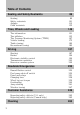
Introduction These are some of the symbols you may see on your vehicle.
Introduction Vehicle Symbol Glossary Power Window Lockout Personal Alarm System Feature Engine Oil Engine Coolant Engine Coolant Temperature Do Not Open When Hot Battery Avoid Smoking, Flames, or Sparks Battery Acid Explosive Gas Fan Warning Power Steering Fluid Maintain Correct Fluid Level MAX MIN Service Engine Soon Engine Air Filter Speed Control Passenger Compartment Air Filter Jack Check Fuel Cap Low Tire Pressure Warning INFORMATION ABOUT THIS GUIDE The information found in this g
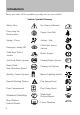
Instrument Cluster Multi-function lever (pg. 52) Instrument cluster (pg. 12) Hazard flasher control (pg. 220) Headlamp control (pg. 40) Steering wheel controls* (pg. 63) Speed controls* (pg. 60) Parking brake release (pg. 195) * if equipped 10 Hood release (pg.
Instrument Cluster Climate controls (pg. 36) Audio system (pg. 19) Auxiliary input jack (pg. 27) Auxiliary power point (pg. 56) Electronic stability control (pg.
Instrument Cluster WARNING LIGHTS AND CHIMES Warning lights and gauges can alert you to a vehicle condition that may become serious enough to cause extensive repairs. A warning light may illuminate when a problem exists with one of your vehicle’s functions. Many lights will illuminate when you start your vehicle to make sure the bulbs work. If any light remains on after starting the vehicle, refer to the respective system warning light for additional information.
Instrument Cluster WARNING: Under engine misfire conditions, excessive exhaust temperatures could damage the catalytic converter, the fuel system, interior floor coverings or other vehicle components, possibly causing a fire. Check fuel cap fill inlet: Illuminates when the fuel cap fill inlet may not be properly closed. Continued driving with this light on may cause the Service engine soon warning light to come on, refer to Easy Fuel “no cap” fuel system in the Maintenance and Specification chapter.
Instrument Cluster WARNING: If the light remains on, continues to flash or fails to illuminate, have the system serviced immediately by an authorized Mazda dealer. With the ABS light on, the anti-lock brake system is disabled but normal braking is still effective unless the brake warning light also remains illuminated with the parking brake released.
Instrument Cluster Low tire pressure warning: Illuminates when your tire pressure is low. If the light remains on at start up or while driving, the tire pressure should be checked. Refer to Inflating your tires in the Tires, Wheels and Loading chapter. When the ignition is first turned to on, the light will illuminate for three seconds to ensure the bulb is working. If the light does not turn on or begins to flash, have the system inspected by your authorized dealer.
Instrument Cluster Door ajar: Illuminates when the ignition is in the on position and any door is open. Turn signal: Illuminates when the left or right turn signal or the hazard lights are turned on. If the indicators flash faster, check for a burned out bulb. High beams: Illuminates when the high beam headlamps are turned on. Key-in-ignition warning chime: Sounds when the key is left in the ignition in the OFF/LOCK or ACCESSORY position and the driver’s door is opened.
Instrument Cluster Speedometer: Indicates the current vehicle speed. Engine coolant temperature gauge: Indicates engine coolant temperature. At normal operating temperature, the needle will be in the normal range (between “H” and “C”). If it enters the red section, the engine is overheating. Stop the vehicle as soon as safely possible, switch off the engine and let the engine cool.
Instrument Cluster Tachometer: Indicates the engine speed in revolutions per minute. Driving with your tachometer pointer continuously at the top of the scale may damage the engine. Fuel gauge: Indicates approximately how much fuel is left in the fuel tank (when the ignition is in the on position). The fuel gauge may vary slightly when the vehicle is in motion or on a grade. The arrow near the fuel pump icon indicates which side of the vehicle the fuel filler door is located.
Entertainment Systems AUDIO SYSTEMS AM/FM/single CD or in-dash CD6/MP3 satellite compatible sound system WARNING: Driving while distracted can result in loss of vehicle control, accident and injury. Mazda strongly recommends that drivers use extreme caution when using any device that may take their focus off the road. The driver’s primary responsibility is the safe operation of their vehicle. Only use cell phones and other devices not essential to the driving task when it is safe to do so.
Entertainment Systems AM/FM Radio / VOL (Power/Volume): Press to turn the radio on/off. Turn the knob to increase/decrease volume. If the volume is set above a certain level and the ignition is turned off, the volume will come back on at a nominal listening level when the ignition is turned back on. AM/FM: Press repeatedly to select AM/FM1/FM2 frequency band. TUNE: Turn the knob to go up/down the frequency band in individual increments. DIRECT: Press DIRECT and then select the desired radio frequency (i.e.
Entertainment Systems To activate the autoset feature: Press MENU repeatedly until AUTO SEEK/TRACK to PRESET ON/OFF appears in the display. Use turn AUTO PRESET ON, and either wait five seconds for the search to initiate or press OK to immediately initiate the search. If you press another control within those five seconds, the search will not initiate; the 10 strongest stations will be filled and the station stored in preset 1 will begin playing.
Entertainment Systems To auto load up to six discs– Press and hold LOAD until the display reads AUTOLOAD #. Load the desired disc, label side up. The system will prompt you to load discs for the remaining available slots. Insert the discs, one at a time, label side up, when prompted. Once loaded, the disc in preset #1 will begin to play. Press the number preset buttons (1–6) to choose the disc you want to play. EJECT: For a single CD system– press EJECT to eject the CD.
Entertainment Systems In MP3 folder mode– Press DIRECT and the memory preset buttons (0–9) of the desired folder. The system will advance to that specific folder. TEXT: In MP3 mode only– Press TEXT repeatedly to view Album (AL), Folder (FL), Song (SO) and Artist (AR) in the display, if available. In TEXT MODE– Sometimes the display requires additional text to be displayed. When the < / > indicator is active, press TEXT and then press SEEK/TRACK to view the additional display text.
Entertainment Systems SEEK/TRACK: Press SEEK/TRACK to seek to the previous/next channel. If a specific category is selected, (Jazz, Rock, News, etc.), press SEEK/TRACK to seek to the previous/next channel in the selected category. Press and hold SEEK/TRACK to fast seek through the previous/next channels. SCAN: Press SCAN for a brief sampling of all available SIRIUS威 satellite channels. If a specific category is selected, (Jazz, Rock, News, etc.
Entertainment Systems SATELLITE RADIO MENU: Press MENU when satellite radio mode is active to access. Press OK to enter into the satellite radio menu. / to cycle through the following options: Press / • CATEGORY MENU- Press OK to enter category mode. Press to scroll through the list of available SIRIUS威 channel Categories (Pop, Rock, News, etc.) Press OK when the desired category appears in the / to search for that display. After a category is selected, press specific category of channels only (i.e. ROCK).
Entertainment Systems d. DISABLE ALERTS/ENABLE ALERTS: Press OK to enable/disable the satellite alert status which alerts you when your selected songs are playing on a satellite radio channel. (The system default is disabled.) SONG ALERTS ENABLED/DISABLED will appear in the display. The menu listing will display the opposite state. For example, if you have chosen to enable the song alerts, the menu listing will read DISABLE as the alerts are currently on, so your other option is to turn them off.
Entertainment Systems FADE: Press SEEK/TRACK to adjust the audio between the back (B) and front (F) speakers. SPEED COMPENSATED VOLUME (if equipped): With this feature on, radio volume automatically gets louder with increasing vehicle speed to compensate for road and wind noise. The default setting is off.
Entertainment Systems Your vehicle is equipped with an Auxiliary Input Jack (AIJ). The Auxiliary Input Jack provides a way to connect your portable music player to the in-vehicle audio system. This allows the audio from a portable music player to be played through the vehicle speakers with high fidelity. To achieve optimal performance, please observe the following instructions when attaching your portable music device to the audio system. Required equipment: 1.
Entertainment Systems 7. Adjust the sound on your portable music player until it reaches the level of the FM station or CD by switching back and forth between the AUX and FM or CD controls. Troubleshooting: 1. Do not connect the audio input jack to a line level output. Line level outputs are intended for connection to a home stereo and are not compatible with the AIJ. The AIJ will only work correctly with devices that have a headphone output with a volume control. 2.
Entertainment Systems • Terrain: Hills, mountains, tall buildings, power lines, electric fences, traffic lights and thunderstorms can interfere with your reception. • Station overload: When you pass a broadcast tower, a stronger signal may overtake a weaker one and play while the weak station frequency is displayed. CD/CD player care Do: • Handle discs by their edges only. (Never touch the playing surface). • Inspect discs before playing. • Clean only with an approved CD cleaner.
Entertainment Systems CDs with homemade paper (adhesive) labels should not be inserted into the CD player as the label may peel and cause the CD to become jammed. It is recommended that homemade CDs be identified with permanent felt tip marker rather than adhesive labels. Ballpoint pens may damage CDs. Please contact your authorized dealer for further information. Audio system warranty and service Refer to the Warranty Guide/Customer Information Guide for audio system warranty information.
Entertainment Systems Sample MP3 structure If you are burning your own MP3 discs, it is important to understand how the system will read the structures you create. While various files may be present, (files with extensions other than mp3), only files with the .mp3 extension will be played. Other files will be ignored by the system. This enables you to use the same MP3 disc for a variety of tasks on your work computer, home computer and your in vehicle system. 1 .mp3 1 .mp3 2 2 3 .mp3 3 .mp3 4 .
Entertainment Systems • Terrain: Hills, mountains, tall buildings, bridges, tunnels, freeway overpasses, parking garages, dense tree foliage and thunderstorms can interfere with your reception. • Station overload: When you pass a ground based broadcast repeating tower, a stronger signal may overtake a weaker one and result in an audio mute. Unlike AM/FM audible static, you will hear an audio mute when there is a satellite radio signal interference.
Entertainment Systems Radio Display ACQUIRING SAT FAULT INVALID CHNL UNSUBSCRIBED NO TEXT 34 Condition Action Required Radio requires more No action required. than two seconds to This message should produce audio for the disappear shortly. selected channel. Internal module or If this message does system failure not clear within a short present. period of time, or with an ignition key cycle, your receiver may have a fault. See your authorized dealer for service.
Entertainment Systems Radio Display NO TEXT NO TEXT NO SIGNAL UPDATING CALL SIRIUS威 1–888–539–7474 Condition Song title information not available. Action Required Song title information not available at this time on this channel. The system is working properly. Category information Category information not available. not available at this time on this channel. The system is working properly.
Climate Controls MANUAL HEATING AND AIR CONDITIONING SYSTEM 1. 2. 3. 4. 5. 6. Fan speed adjustment: Turn to select fan speed. R Rear defroster: Press to activate/deactivate the rear window defroster. Refer to Rear window defroster later in this chapter for more information. Defrost: Distributes outside air through the windshield defroster vents and demister vents. Can be used to clear the windshield of fog and thin ice. The system will automatically provide outside air to reduce window fogging.
Climate Controls 10. Passenger heated seat control (if equipped): Press to activate/deactivate the passenger heated seat. See Heated seats in the Seating and Safety Restraints chapter. Recirculated air: Press to activate/deactivate air recirculation in the vehicle. Recirculated air may reduce the amount of time needed to cool down the interior of the vehicle and may also help reduce undesired odors from reaching the interior of the vehicle.
Climate Controls Operating tips • To reduce fog build up on the windshield during humid weather, select (defrost) or (floor/defrost). • To reduce humidity build up inside the vehicle, do not drive with the (recirculated air) engaged and A/C off. system off or with • Do not put objects under the front seats that will interfere with the airflow to the back seats. • Remove any snow, ice or leaves from the air intake area at the base of the windshield.
Climate Controls REAR WINDOW DEFROSTER R The rear defroster control is located on the climate control panel and works to clear the rear window of fog and thin ice. The engine must be running to operate the rear window defroster. to turn the rear window defroster on. An indicator light on the Press R button will illuminate when active.
Lights HEADLAMP CONTROL Rotate the headlamp control to the to turn on the first position parking lamps. Rotate to the second position turn on the headlamps. Rotate back to headlamps off. to to turn the Autolamp control The autolamp system provides light sensitive automatic on-off control of the exterior lights normally controlled by the headlamp control. The autolamp system is factory programmed to keep the lights on for 20 seconds after the ignition switch is turned to off.
Lights Autolamp delay system With autolamps, you can set the delay time to keep the headlights on for up to three minutes after the key is turned off. The delay time is set to 20 seconds at the factory, but the delay time may be changed by following the steps below (Steps 1 through 6 must be done within 10 seconds). 1. Turn the key to the off position. 2. Rotate the headlamp control to the autolamp position. 3. Rotate the headlamp control to the off position. 4. Turn the key to the on position. 5.
Lights Flash to pass Pull toward you slightly to activate and release to deactivate. Daytime running lamps (DRL) (if equipped) Turns the lowbeam headlamps on with a reduced output. To activate: • the ignition must be in the on position. • the headlamp control must be in the off, parking lamps or autolamp position. • with automatic transmission, the transmission is not in P (Park), • with manual transmission, the parking brake must be released.
Lights Note: If the battery is disconnected, discharged, or a new battery is installed, the dimmer switch requires re-calibration. Rotate the dimmer switch from the full dim position to the full dome/on position to reset. This will ensure that your displays are visible under all lighting conditions. AIMING THE HEADLAMPS The headlamps on your vehicle are properly aimed at the assembly plant. If your vehicle has been in an accident the alignment of your headlamps should be checked by your authorized dealer.
Lights 4. On the wall or screen you will observe a light pattern with a distinct horizontal edge of high intensity light towards the right. If this edge is not at the horizontal reference line, the beam will need to be adjusted. 5. Locate the vertical adjuster on the headlamp, then use a 4 mm socket to turn the adjuster either counterclockwise (to adjust up) or clockwise (to adjust down) aligning the upper edge of the light pattern to the horizontal line. 6.
Lights INTERIOR LAMPS Dome lamps and map lamps The front dome lamp is located overhead between the driver and passenger seats. The dome lamp is preset to illuminate when a door is opened and will remain on for 25 seconds after the door is closed. To manually turn on the dome lamp, rotate the panel dimmer control, located on the instrument panel, to the full upright position past the detent. To turn off the domelamp, rotate the panel dimmer control to the full down position past the detent.
Lights Cargo and dome lamp Rear cargo lamp equipped with an ON/OFF/DOOR control will light when: • the doors are closed and the control is in the ON position. • the control is in the DOOR position and any door is open. When the control is in the OFF position, it will not illuminate when you open the doors. BULB REPLACEMENT Lamp assembly condensation Exterior lamps are vented to accommodate normal changes in pressure. Condensation can be a natural by-product of this design.
Lights Function Number of bulbs Trade number Headlamps (high and 2 H13 low beams) Park/turn/sidemarker 2 3457A (amber) lamps (front) Rear 2 3157K / 4157K stop/tail/sidemarker Backup lamp 2 921 Fog lamp (front) 2 9145 Center High-mount 5 W5WL stop lamp Rear license plate 2 168 lamp All replacement bulbs are clear in color except where noted. To replace all instrument panel lights - see your authorized dealer Replacing interior bulbs Check the operation of the interior bulbs frequently.
Lights WARNING: Handling Halogen Bulbs: When a halogen bulb breaks, it is dangerous. These bulbs contain pressurized gas. If one is broken, it will explode and serious injuries could be caused by the flying glass. If the glass portion of the bulb is touched with bare hands, body oil could cause the bulb to overheat and explode when lit. Never touch the glass portion of the bulb with your bare hands and always wear eye protection when handling or working around halogen bulbs. 5.
Lights Replacing tail/stop/turn/backup lamp bulbs The tail/stop/turn/sidemarker/backup lamp bulbs are located in the same portion of the tail lamp assembly, one just below the other. Follow the same steps to replace either bulb: 1. Make sure the headlamp switch is in the off position, then open the liftgate to expose the lamp assembly screws. 2. Remove the two screws from the lamp assembly. 3.
Lights 4. Pull bulb straight out of socket and push in the new bulb. 5. Install the bulb socket into the lamp assembly and rotate clockwise. 6. To install, carefully press the lamp assembly into liftgate. Replacing high-mount brake lamp bulbs To remove the lamp assembly: 1. Remove the two screws and move the lamp assembly away from the liftgate. 2. Remove the bulb holder from the lamp assembly by pressing the snaps. 3. Pull the bulb straight out of the socket and push in the new bulb.
Lights Replacing fog lamp bulbs (if equipped) 1. Make sure the fog lamp switch is in the off position. 2. From underneath the vehicle, rotate the harness/bulb assembly counterclockwise, to remove from the fog lamp. 3. Carefully disconnect the bulb from the harness assembly via the two snap clips. Install the new bulb in reverse order.
Driver Controls MULTI-FUNCTION LEVER Windshield wiper: Rotate the end of the control away from you to increase the speed of the wipers; rotate towards you to decrease the speed of the wipers. Note: Heavy ice and snow can jam the wiper blades and overheat the wiper motor. If this happens, the motor will automatically stop the operation of the blades for a short period of time. If this happens while driving, turn off the wiper switch, park off the right-of-way, and remove the snow and ice.
Driver Controls Rear window wiper/washer controls For rear wiper operation, rotate the rear window wiper and washer control to the desired position. Select: 2 — Normal speed operation of rear wiper. 1 — Intermittent operation of rear wiper. O (off) — Rear wiper and washer off. For rear wash cycle, rotate (and hold as desired) the rear wiper/washer control to either position. From either position, the control will automatically return to the INT 2 or O (off) position.
Driver Controls WARNING: Adjusting the steering wheel while the vehicle is moving is dangerous. Moving it can very easily cause the driver to abruptly turn to the left or right. This can lead to loss of control or an accident. Never adjust the steering wheel while the vehicle is moving. ILLUMINATED VISOR MIRROR (IF EQUIPPED) Lift the mirror cover to turn on the visor mirror lamps. Slide on rod feature The visor will slide back and forth on the rod for increased sunlight coverage.
Driver Controls OVERHEAD CONSOLE (IF EQUIPPED) The appearance of your vehicle’s overhead console will vary according to your option package. Storage compartment (if equipped) Press the release on the door to open the storage compartment. The storage compartment may be used to secure sunglasses or a similar object. CENTER CONSOLE Your vehicle is equipped with a variety of console features. These include: 1. Cupholders 2.
Driver Controls The tray and inside bin can be removed to open up space to fit a laptop computer, MP3 players, CDs or handbags. To remove, open the console lid and pull the bin straight up and out from the console housing. The sliding tray and inside bin can be hooked on the side or rear of the console for extra storage. AUXILIARY POWER POINT (12VDC) Power outlets are designed for accessory plugs only. Do not insert any other object in the power outlet as this will damage the outlet and blow the fuse.
Driver Controls To have full capacity usage of your power point, the engine is required to be running to avoid unintentional discharge of the battery. To prevent the battery from being discharged: • do not use the power point longer than necessary when the engine is not running, • do not leave battery chargers, video game adapters, computers and other devices plugged in overnight or when the vehicle is parked for extended periods. Always keep the power point caps closed when not being used.
Driver Controls One-touch down (AUTO) Allows the driver’s window to open fully without holding the control down. Press the switch completely down to the second detent and release quickly. The window will open fully. Momentarily press the switch to any position to stop the window operation. Window lock The window lock feature allows only the driver to operate the power windows. To lock out all the window controls (except for the driver’s) press the right side of the control.
Driver Controls Automatic dimming interior rear view mirror (if equipped) Your vehicle may be equipped with an interior rear view mirror that has an auto-dimming function. The electronic day/night mirror will change from the normal (high reflective) state to the non-glare (darkened) state when bright lights (glare) reach the interior mirror. When the interior mirror detects bright light from behind the vehicle, it will automatically adjust (darken) to minimize glare.
Driver Controls Fold-away mirrors Fold the side mirrors in carefully when driving through a narrow space, like an automatic car wash. Heated outside mirrors (if equipped) Both mirrors are heated automatically to remove ice, mist and fog when the rear window defrost is activated. Do not remove ice from the mirrors with a scraper or attempt to readjust the mirror glass if it is frozen in place. These actions could cause damage to the glass and mirrors.
Driver Controls Setting speed control The controls for using your speed control are located on the steering wheel for your convenience. 1. Press the ON control and release it. 2. Accelerate to the desired speed. 3. Press the SET + control and release it. 4. Take your foot off the accelerator pedal. on the 5. The indicator light instrument cluster will turn on. Note: • Vehicle speed may vary momentarily when driving up and down a steep hill.
Driver Controls Resuming a set speed Press the RES control and release it. This will automatically return the vehicle to the previously set speed. Increasing speed while using speed control There are three ways to set a higher speed: • Press and hold the SET + control until you get to the desired speed, then release the control. • Press and release the SET + control to operate the Tap-Up function. Each tap will increase the set speed by 1 mph (1.6 km/h).
Driver Controls Turning off speed control There are two ways to turn off the speed control: • Press the OFF control. • Turn off the ignition. Note: When you turn off the speed control or the ignition, your speed control set speed memory is erased. STEERING WHEEL CONTROLS (IF EQUIPPED) These controls allow you to operate some audio control features. Radio control features Press MEDIA to select: • AM, FM1, FM2, or CD • SAT1, SAT2 or SAT3 (Satellite Radio mode if equipped).
Driver Controls In any mode: • Press VOL + or VOL - to adjust the volume. MOON ROOF (IF EQUIPPED) You can move the glass panel of the moon roof back to open or tilt up (from the closed position) to ventilate the vehicle. WARNING: Do not let children play with the moon roof or leave children unattended in the vehicle. They may seriously hurt themselves. To open the moon roof: The moon roof is equipped with an automatic, one-touch, opening, closing and venting feature.
Driver Controls If the ignition is turned off (without accessory delay being active) during bounce-back, the moon roof will move until the bounce-back position is reached. Bounce-back override: To override bounce-back, press and hold the front portion of the control. For example: Bounce-back can be used to overcome the resistance of ice on the moon roof or seals.
Driver Controls UNIVERSAL GARAGE DOOR OPENER (IF EQUIPPED) Your vehicle may be equipped with a universal garage door opener which can be used to replace the common hand-held transmitter. Car2U姞 Home Automation System (if equipped) The Car2U威 Home Automation System is a universal transmitter located in the driver’s visor that includes two primary features – a garage door opener and a platform for remote activation of devices within the home.
Driver Controls Types of garage door openers (rolling code and fixed code) The Car2U威 Home Automation System may be programmed to operate rolling code and fixed code garage door openers. • Rolling code garage door openers were produced after 1996 and are code protected. Rolling code means the coded signal is changed every time your remote control garage door opener is used. • Fixed code garage door openers were produced prior to 1996. Fixed code uses the same coded signal every time.
Driver Controls 1. Firmly press the two outer Car2U威 system buttons for 1–2 seconds, then release. 2. Go to the garage to locate the garage door opener motor and its “learn” button. You may need a ladder to reach the unit and you may need to remove the unit’s cover or light lens to locate the “learn” button. Press the “learn” button, after which you will have 10–30 seconds to return to your vehicle and complete the following steps.
Driver Controls The indicator light above the selected button will turn on to confirm that the Car2U威 system is responding to the button command. To program another rolling code device such as an additional garage door opener, a security device or home lighting, repeat Steps 1 through 4 substituting a different function button in Step 3 than what you used for the garage door opener.
Driver Controls Switch position 1 2 3 4 Up, on L L L L or + Middle, neutral M M M M or 0 Down, R R R R off or – L=left; M=middle; R=right 5 6 7 8 9 10 11 12 L L L L L L L L M M M M M M M M R R R R R R R R 3. To input these positions into the Car2U威 system, simultaneously press all three Car2U威 system buttons for a few seconds and then release to put the device into programming mode. The indicator lights will blink slowly. Within 2.
Driver Controls After successful programming, you will be able to operate your Car2U威 system by pressing the button you programmed to activate the opener. The indicator light above the selected button will turn on to confirm that the Car2U威 system is responding to the button command. Erasing the Car2U姞 Home Automation System buttons Note: The system allows for three devices to be programmed.
Driver Controls LIFTGATE • To open the liftgate window, unlock the liftgate (with the power door locks or the remote entry) and press the right side control button located under the license plate lamp shield. • To open the liftgate, unlock the liftgate (with the power door locks or the remote entry) and press the middle control button located below the license plate. To lock the liftgate and the liftgate window, use the power door locks.
Driver Controls CARGO AREA FEATURES Cargo shade (if equipped) If your vehicle has a cargo shade, you can use it to cover items in the cargo area of your vehicle. To install the shade: • Insert the ends of the cargo shade into the mounting features located behind the rear seat on the rear trim panels. To operate the shade: 1. Grasp the handle at the rear edge of the shade and pull rearward. 2. Secure both ends of the support rod into the retention slots located on the rear quarter trim panels.
Driver Controls Passenger side cargo compartment Your vehicle is equipped with a passenger side cargo compartment located in the right rear trim panel which is used to store small items and may have the Easy Fuel™ white plastic funnel attached on the inside of the access door. Make sure the access door is secured so it does not rattle when you drive. ROOF RACK SYSTEM (IF EQUIPPED) Loads should never be placed directly on the roof panel.
Driver Controls To remove the cross-bar assembly (if equipped) from the roof rack side rails: 1. Loosen the thumbwheel at both ends of the cross-bar (both cross-bars are adjustable). 2. Slide the cross-bar to the end of the rail. 3. Use a long, flat object to depress the tongue in the endcaps on both sides of the cross-bar. 4. Slide the cross-bar assembly off the end of the rail.
Driver Controls To reinstall the cross-bar assembly (if equipped) to the roof rack side rails: 1. Ensure that both cross-bar assemblies are installed with the F (front) arrow facing towards the front of the vehicle. 2. Use a long, flat object to depress the tongue in the endcaps on both sides of the cross-bar. 3. Slide the cross-bar assemblies over the end cap tongue and into the side rails. 4. Tighten thumbwheel at both ends of the cross-bar.
Locks and Security KEYS Your vehicle is equipped with two Integrated Keyhead Transmitters (IKTs). The key blade functions as a programmed key which starts the vehicle and unlocks/locks all the doors. The transmitter portion functions as the remote entry transmitter. Your IKTs are programmed to your vehicle; using a non-programmed key will not permit your vehicle to start. If you lose your authorized dealer supplied IKTs, replacement IKTs are available through your authorized dealer.
Locks and Security POWER DOOR LOCKS • Press the doors. control to unlock all • Press the doors. control to lock all Door key unlocking/locking Unlocking the doors Turn the key in the door cylinder to unlock the driver’s door only. All other doors will remain locked. Locking the doors Turn the key in the door cylinder to lock the driver’s door only.
Locks and Security Power door unlock/lock procedure You must complete Steps 1-5 within 30 seconds or the procedure will have to be repeated. If the procedure needs to be repeated, you must wait 30 seconds. Note: All doors must be closed and remain closed throughout the configuration process. 1. The ignition must be off to begin sequence. 2. Turn the ignition to the on position. 3. Press the power door unlock control three times. 4. Turn the ignition from the on to the off position. 5.
Locks and Security Deactivating/activating autounlock Your vehicle comes with the autounlock feature activated. There are two methods to enable/disable this feature: • Through your authorized dealer, or • by using the power door unlock/lock sequence. Note: The autounlock feature can be activated/deactivated independently of the autolock feature. Power door lock switch autounlock enable/disable procedure Before starting, ensure the ignition is in the off position and all vehicle doors are closed.
Locks and Security CHILDPROOF DOOR LOCKS When these locks are set, the rear doors cannot be opened from the inside. The rear doors can be opened from the outside when the doors are unlocked. The childproof locks are located on rear edge of each rear door and must be set separately for each door. Note: Setting the lock for one door will not automatically set the lock for both doors so you must set each child lock on each door separately.
Locks and Security The IKT allows you to: • remotely unlock the vehicle doors. • remotely lock all the vehicle doors. • remotely open the power liftgate glass. • activate the personal alarm. • operate the illuminated entry feature. The remote entry lock/unlock feature operates in any ignition position except while the key is held in the start position. The panic feature operates with the key in the off position.
Locks and Security Locking the doors 1. Press and release to lock all the doors. Assuming all vehicle doors and the liftgate are properly closed, the parking lamps will illuminate. 2. Press and release again within three seconds to confirm that all the doors and liftgate are closed and locked. Note: The doors will lock again and the horn will chirp once. If any of the doors or the liftgate are not properly closed, the horn will chirp twice and turn lamps will not illuminate when the control is pressed.
Locks and Security To replace the battery: 1. Twist a thin coin in the slot of the IKT near the key ring in order to remove the battery cover. Note: Do not wipe off any grease on the battery terminals on the back surface of the circuit board. 2. Remove the old battery. Note: Please refer to local regulations when disposing of transmitter batteries. 3. Insert the new battery. Refer to the instructions inside the IKT for the correct orientation of the battery.
Locks and Security The illuminated entry system will turn off the lights if: • the ignition is turned to the on position, or • the Integrated Keyhead Transmitter lock control is pressed, or • the vehicle is locked using the keyless entry keypad (if equipped), or • after 25 seconds of illumination. The lights will not turn off if: • they have been turned on with the dimmer control, or • any door is open. Illuminated exit • The lamps will illuminate when the key is removed from the ignition.
Locks and Security Note: Do not leave a duplicate coded key in the vehicle. Always take your keys and lock all doors when leaving the vehicle. Anti-theft indicator The anti-theft indicator is located in the instrument panel cluster. • When the ignition is in the off position, the indicator will flash once every two seconds to indicate the SecuriLock威 system is functioning as a theft deterrent.
Locks and Security Replacement Integrated Keyhead Transmitters (IKT) and coded keys Note: Your vehicle comes equipped with two Integrated Keyhead Transmitters (IKTs). The IKT functions as both a programmed ignition key that operates all the locks and starts the vehicle, as well as a remote keyless entry transmitter. A maximum of eight coded keys can be programmed to your vehicle; only four of these eight keys can be IKTs with remote entry functionality.
Locks and Security Please read and understand the entire procedure before you begin. 1. Insert the first previously programmed coded key into the ignition. 2. Turn the ignition from the 1 (off) position to the 3 (on) position. Keep the ignition in the 3 (on) position for at least three seconds, but no more than 10 seconds. 3. Turn the ignition to the 1 (off) position and remove the first coded key from the ignition. 4.
Seating and Safety Restraints FRONT SEATS WARNING: Reclining the seatback can cause an occupant to slide under the seat’s seat belt, resulting in severe personal injuries in the event of a collision. WARNING: Do not pile cargo higher than the seatbacks to reduce the risk of injury in a collision or sudden stop. WARNING: Before returning the seatback to its original position, make sure that cargo or any objects are not trapped behind the seatback.
Seating and Safety Restraints To adjust the head restraint, do the following: 1. Adjust the seatback to an upright driving/riding position. 2. Raise the head restraint by pulling up on the head restraint. 3. Lower the head restraint by pressing and holding the guide sleeve adjust/release button and pushing down on the head restraint. Properly adjust the head restraint so that the top of the head restraint is even with the top of your head and positioned as close as possible to the back of your head.
Seating and Safety Restraints To remove the adjustable head restraint, do the following: 1. Pull up the head restraint until it reaches the highest adjustment position. 2. Simultaneously press and hold both the adjust/release button and the unlock/remove button, then pull up on the head restraint. To reinstall the adjustable head restraint, do the following: 1. Insert the two stems into the guide sleeve collars. 2. Push the head restraint down until it locks.
Seating and Safety Restraints WARNING: To minimize the risk of neck injury in the event of a crash, head restraints must be installed properly. Adjusting the front manual seat (if equipped) Lift handle to move seat forward or backward. Pull lever up to adjust seatback. Using the manual lumbar support (if equipped) The lumbar support control is located on the inboard side of the driver’s seatback. Turn the lumbar support control clockwise to increase firmness.
Seating and Safety Restraints Adjusting the front power seat (if equipped) WARNING: Never adjust the driver’s seat or seatback when the vehicle is moving. You could move out of position to control the vehicle. Then a serious accident could occur. Sudden braking or a collision could cause serious injury. Adjust the seat only when the vehicle is stopped. WARNING: Do not pile cargo higher than the seatbacks to reduce the risk of injuring people in a collision or sudden stop.
Seating and Safety Restraints The control is located on the outboard side of the seat cushion. Move the front of the control up or down to raise or lower the front portion of the seat cushion. Move the rear of the control up or down to raise or lower the rear portion of the seat cushion. Move the control in the directions shown to move the seat forward, backward, up or down.
Seating and Safety Restraints Note: Do not do the following: • Place heavy objects on the seat • Operate the seat heater if water or any other liquid is spilled on the seat. Allow the seat to dry thoroughly. To operate the heated seats: • Press the button located on the instrument panel to activate. • Press again to deactivate. The heated seats will activate when the ignition is in the on position and the engine is running.
Seating and Safety Restraints To adjust the head restraint, do the following: 1. Adjust the seatback to an upright driving/riding position. 2. Raise the head restraint by pulling up on the head restraint. 3. Lower the head restraint by pressing and holding the guide sleeve adjust/remove button and pushing down on the head restraint. Properly adjust the head restraint so that the top of the head restraint is even with the top of your head and positioned as close as possible to the back of your head.
Seating and Safety Restraints To remove the adjustable head restraint, do the following: 1. Pull up the head restraint until it reaches the highest adjustment position. 2. Press and hold the adjust/remove button, then pull up on the head restraint. To reinstall the adjustable head restraint, do the following: 1. Insert the two stems into the guide sleeve collars. 2. Push the head restraint down until it locks.
Seating and Safety Restraints WARNING: To minimize the risk of neck injury in the event of a crash, head restraints must be installed properly. Folding down second row seats 1. Remove the second row head restraint. See Second row adjustable head restraints in this chapter. Note: Place the head restraint underneath the back of the front seat for storage. 2. Pull the seat release strap. Note: Make sure the floor is clear of all objects before folding the seat. 3. Flip seat forward.
Seating and Safety Restraints Attach the seat belt web snap button to the quarter trim panel snap button. This will ensure that seat belt does not get caught by staying out of the seat back folding path. 4. To release seatback, pull the seatback release lever (on top of seat) toward the front seat. This is common for both 60% and 40% seatbacks. Note: When the seatback release lever is pulled, slowly lower seatback to the flat position. 5. Rotate seatback down into load floor position.
Seating and Safety Restraints Returning the second row seats to upright position 1. Pull seatback up and into upright position making sure seatback locks into place and the red seat unlatched indicator on release paddle is not visible. 2. Rotate seat cushion down into the seating position making sure that the seat cushion is locked into place and that the seat belt buckles are exposed. WARNING: Make sure seat belt buckle heads are through elastic holders on seat backs.
Seating and Safety Restraints 4. Remove the second row head restraint from underneath the front seat and reinstall. See Second row adjustable head restraints in this chapter. To remove the second row cushion 1. Lift the yellow tab to release the hinges. 2. Pull the cushion to the outboard side of the vehicle. To install the second row cushion 1. Push the cushion to the inboard side of the vehicle. 2. Make sure that the hinges are locked into place.
Seating and Safety Restraints • • • • • • Front passenger sensing system “Passenger airbag off” or “pass airbag off” indicator lamp Front crash severity sensor. Restraints Control Module (RCM) with impact and safing sensors. Restraint system warning light and back-up tone. The electrical wiring for the airbags, crash sensor(s), seat belt pretensioners, front seat belt usage sensors, driver seat position sensor, front passenger sensing system, and indicator lights.
Seating and Safety Restraints Driver’s seat position sensor The driver’s seat position sensor allows your Personal Safety System™ to tailor the deployment level of the driver dual-stage airbag based on seat position. The system is designed to help protect smaller drivers sitting close to the driver airbag by providing a lower airbag output level.
Seating and Safety Restraints Front seat belt usage sensors The front seat belt usage sensors detect whether or not the driver and front outboard passenger seat belts are fastened. This information allows your Personal Safety System™ to tailor the airbag deployment and seat belt pretensioner activation depending upon seat belt usage. Refer to Safety restraints section in this chapter.
Seating and Safety Restraints If any of these things happen, even intermittently, have the Personal Safety System™ serviced at an authorized dealer immediately. Unless serviced, the system may not function properly in the event of a collision. Safety restraints precautions WARNING: Always drive and ride with your seatback upright and the lap belt snug and low across the hips and the shoulder belt snug across the chest.
Seating and Safety Restraints WARNING: Placing a child, 12 years or younger, in the front seat is dangerous. The child could be hit by a deploying airbag and be seriously injured or even killed. A sleeping child is more likely to lean against the door and be hit by the side airbag (if equipped) in a moderate collision. Whenever possible, always secure a child, 12 years or younger, in the rear seat, with an appropriate child restraint system for the child’s age and size.
Seating and Safety Restraints • This seat belt system has a retractor assembly that is designed to pay out webbing in a controlled manner. This feature is designed to help reduce the belt force acting on the occupant’s chest. All seat belts in the vehicle are combination lap and shoulder belts.
Seating and Safety Restraints • Grasp the shoulder portion and pull downward until the entire belt is pulled out. • Allow the belt to retract. As the belt retracts, you will hear a clicking sound. This indicates the seat belt is now in the automatic locking mode. How to disengage the automatic locking mode Disconnect the combination lap/shoulder belt and allow it to retract completely to disengage the automatic locking mode and activate the vehicle sensitive (emergency) locking mode.
Seating and Safety Restraints Seat belt height adjustment Your vehicle has seat belt height adjustments at the front outboard seating positions. Adjust the height of the shoulder belt so the belt rests across the middle of your shoulder. To adjust the shoulder belt height, squeeze and hold the buttons on the side and slide the height adjuster up or down. Release the buttons and pull down on the height adjuster to make sure it is locked in place.
Seating and Safety Restraints WARNING: Failure to replace both front restraints under the above conditions could result in severe personal injuries in the event of a collision. The seat belt pretensioners will only function once. After they are deployed, they will not work again and must be replaced immediately, even if there was no front seat occupant seated at the time. WARNING: Modifying the components or wiring of the pretensioner system, including the use of electronic testing devices is dangerous.
Seating and Safety Restraints Conditions of operation If... The driver’s seat belt is not buckled before the ignition switch is turned to the on position... The driver’s seat belt is buckled while the indicator light is illuminated and the warning chime is sounding... The driver’s seat belt is buckled before the ignition switch is turned to the on position... Then... The seat belt warning light illuminates 1 minute and the warning chime sounds 6 seconds.
Seating and Safety Restraints If... The driver’s and front passenger’s seat belts are buckled before the ignition switch is turned to the on position or less than 1-2 minutes have elapsed since the ignition switch has been turned to on... The driver’s or front passenger’s seat belt is not buckled when the vehicle has reached at least 3 mph (5 km/h) and 1-2 minutes have elapsed since the ignition switch has been turned to on...
Seating and Safety Restraints The following are reasons most often given for not wearing seat belts (All statistics based on U.S. data): Reasons given... ⬙Crashes are rare events⬙ ⬙I’m not going far⬙ ⬙Belts are uncomfortable⬙ ⬙I was in a hurry⬙ ⬙Seat belts don’t work⬙ ⬙Traffic is light⬙ ⬙Belts wrinkle my clothes⬙ ⬙The people I’m with don’t wear belts⬙ Consider... 36,700 crashes occur every day. The more we drive, the more we are exposed to ⬙rare⬙ events, even for good drivers.
Seating and Safety Restraints Reasons given... ⬙I have an airbag⬙ ⬙I’d rather be thrown clear⬙ Consider... Airbags offer greater protection when used with seat belts. Frontal airbags are not designed to inflate in rear and side crashes or rollovers. Not a good idea. People who are ejected are 40 times more likely to DIE. Seat belts help prevent ejection, WE CAN’T ⬙PICK OUR CRASH⬙. WARNING: Do not sit on top of a buckled seat belt or insert a latchplate into the buckle to avoid the Belt-Minder威 chime.
Seating and Safety Restraints 1. Turn the ignition switch to the on position. DO NOT START THE ENGINE. 2. Wait until the seat belt warning light turns off (Approximately one minute). • Step 3 must be completed within 30 seconds after the seat belt warning light turns off. 3. For the seating position being disabled, buckle then unbuckle the seat belt three times, ending in the unbuckled state. • After Step 3, the seat belt warning light will be turned on for three seconds. 4.
Seating and Safety Restraints Important supplemental restraint system (SRS) precautions The supplemental restraint system is designed to work with the seat belt to help protect the driver and right front passenger from certain upper body injuries. WARNING: Airbags DO NOT inflate slowly or gently and the risk of injury from a deploying airbag is greatest close to the trim covering the airbag module.
Seating and Safety Restraints WARNING: Do not put anything on or over the airbag module including hands or feet. Placing objects on or over the airbag inflation area may cause those objects to be propelled by the airbag into your face and torso causing serious injury. WARNING: Do not attempt to service, repair, or modify the Airbag Supplemental Restraint Systems or its fuses. See your authorized Mazda dealership.
Seating and Safety Restraints WARNING: Airbags can kill or injure a child in a child seat. NEVER place a rear-facing child seat in front of an active airbag. If you must use a forward-facing child seat in the front seat, move the seat all the way back. Secure the seat and the child in it properly.
Seating and Safety Restraints extremely important that occupants be properly restrained as far away from the airbag module as possible while maintaining vehicle control. WARNING: Several airbag system components get hot after inflation. Do not touch them after inflation or you may be burned. WARNING: If the airbag and seat belt pretensioners have deployed, the airbag or seat belt pretensioners will not function again and must be replaced immediately.
Seating and Safety Restraints Front passenger sensing system The front passenger sensing system is designed to meet the regulatory requirements of Federal Motor Vehicle Safety Standard (FMVSS) 208 and is designed to disable (will not inflate) the front passenger’s frontal airbag under certain conditions. The front passenger sensing system works with sensors that are part of the front passenger’s seat and seat belt.
Seating and Safety Restraints • When the front passenger sensing system disables (will not inflate) the front passenger frontal airbag, the indicator lamp will illuminate and stay lit to remind you that the front passenger frontal airbag is disabled. • If the child restraint has been installed and the indicator lamp is not lit, then turn the vehicle off, remove the child restraint from the vehicle and reinstall the restraint following the child restraint manufacturer’s instructions.
Seating and Safety Restraints WARNING: Even with Advanced Restraints Systems, children 12 and under should be properly restrained in a rear seating position. After all occupants have adjusted their seats and put on seat belts, it’s very important that they continue to sit properly. A properly seated occupant sits upright, leaning against the seat back, and centered on the seat cushion, with their feet comfortably extended on the floor. Sitting improperly can increase the chance of injury in a crash event.
Seating and Safety Restraints • Objects between the seat cushion and the center console (if equipped) • Objects hanging off the seat back • Objects stowed in the seatback map pocket (if equipped) • Objects placed on the occupant’s lap • Cargo interference with the seat • Other passengers pushing or pulling on the seat • Rear passenger feet and knees resting or pushing on the seat The conditions listed above may cause the weight of a properly seated occupant to be incorrectly interpreted by the front passeng
Seating and Safety Restraints • Restart the vehicle. • Wait at least 2 minutes and verify that the airbag readiness lamp is no longer illuminated • If the airbag readiness lamp remains illuminated, this may or may/not be a problem due to the front passenger sensing system. DO NOT attempt to repair or service the system; take your vehicle immediately to an authorized Mazda dealer. Ask the front seat occupant to sit in a rear seat until the air bag system if checked by the authorized Mazda Dealer.
Seating and Safety Restraints Seat-mounted side airbag system WARNING: Do not place objects or mount equipment on or near the airbag cover on the side of the seatbacks of the front seats or in front seat areas that may come into contact with a deploying airbag. Failure to follow these instructions may increase the risk of personal injury in the event of a collision. WARNING: Do not use accessory seat covers or non-Mazda leather seat upgrade kits.
Seating and Safety Restraints How does the side airbag system work? The design and development of the side airbag system included recommended testing procedures that were developed by a group of automotive safety experts known as the Side Airbag Technical Working Group. These recommended testing procedures help reduce the risk of injuries related to the deployment of side airbags.
Seating and Safety Restraints WARNING: Several airbag system components get hot after inflation. Do not touch them after inflation. WARNING: If the side airbag has deployed, the airbag will not function again. The side airbag system (including the seat) must be inspected and serviced by an authorized dealer. If the airbag is not replaced, the unrepaired area will increase the risk of injury in a collision.
Seating and Safety Restraints Side-curtain airbag system WARNING: Do not place objects or mount equipment on or near the headliner at the siderail that may come into contact with a deploying side-curtain airbags. Failure to follow these instructions may increase the risk of personal injury in the event of a collision. WARNING: Do not lean your head on the door or window glass. The side-curtain airbags could injure you as it deploys from the headliner.
Seating and Safety Restraints How do the side-curtain airbags work? The design and development of the side air curtain system included recommended testing procedures that were developed by a group of automotive safety experts known as the Side Airbag Technical Working Group. These recommended testing procedures help reduce the risk of injuries related to the deployment of side airbags (including side air curtain systems).
Seating and Safety Restraints The side-curtain airbags are mounted to roof side-rail sheet metal, behind the headliner, above the first and second row seats. In certain lateral collisions or rollover events, the side-curtain airbags will be activated, regardless of which seats are occupied. In certain rollover events, the side-curtain airbag on both sides of the vehicle will be inflated, regardless of which seats are occupied.
Seating and Safety Restraints A difficulty with the system is indicated by one or more of the following: • The readiness light (same light as for front airbag system) will either flash or stay lit. • The readiness light will not illuminate immediately after ignition is turned on. • A series of five beep sounds will be heard. The tone pattern will repeat periodically until the problem and light are repaired.
Seating and Safety Restraints SAFETY RESTRAINTS FOR CHILDREN See the following sections for directions on how to properly use safety restraints for children. Also see Airbag supplemental restraint system (SRS) in this chapter for special instructions about using airbags. Important child restraint precautions WARNING: Always make sure your child is secured properly in a device that is appropriate for their height, age and weight. Child safety restraints must be purchased separately from the vehicle.
Seating and Safety Restraints Recommendations for Safety Restraints for Children Recommended Child size, height, weight, or age restraint type Infants or Children weighing 40 lb (18 kg) or Use a child safety toddlers less (generally age four or younger) seat (sometimes called an infant carrier, convertible seat, or toddler seat). Small Children who have outgrown or no Use a children longer properly fit in a child safety belt-positioning seat (generally children who are less booster seat.
Seating and Safety Restraints Recommendations for attaching child safety restraints for children Restraint Type Rear facing child seat Forward facing child seat Forward facing child seat Use any attachment method as indicated below by “X” LATCH LATCH Seat Seat belt Seat (lower (lower belt and belt Child anchors anchors and LATCH only Weight and only) top (lower top tether anchors tether anchor and top anchor) tether anchor) Up to 48 lb X X (21 kg) Up to 48 lb X X X (21 kg) Over 48 lb X X (21 kg) WARNING
Seating and Safety Restraints WARNING: Always carefully follow the instructions and warnings provided by the manufacturer of any child restraint to determine if the restraint device is appropriate for your child’s size, height, weight, or age. Follow the child restraint manufacturer’s instructions and warnings provided for installation and use in conjunction with the instructions and warnings provided by the vehicle manufacturer.
Seating and Safety Restraints training to ensure that all children ages 0 to 16 are properly restrained in the correct restraint system. Mazda recommends checking with a NHTSA Certified Child Passenger Safety Technician (CPST) and your pediatrician to make sure your seat is appropriate for your child and properly installed in the vehicle. To locate a child seat fitting station and CPST contact the NHTSA toll free at 1-888-327-4236 or on the internet at http://www.nhtsa.dot.gov.
Seating and Safety Restraints Airbags can kill or injure a child in a child seat. NEVER place a rear-facing child seat in front of an active airbag. If you must use a forward-facing child seat in the front seat, move the vehicle seat all the way back. Children 12 and under should be properly restrained in a rear seating position whenever possible. If all children cannot be seated and restrained properly in a rear seating position, properly restrain the largest child in the front seat.
Seating and Safety Restraints Perform the following steps when installing the child seat with combination lap/shoulder belts: Note: Although the child seat illustrated is a forward facing child seat, the steps are the same for installing a rear facing child seat. 1. Position the child safety seat in a seat with a combination lap and shoulder belt. 2. Pull down on the shoulder belt and then grasp the shoulder belt and lap belt together.
Seating and Safety Restraints 3. While holding the shoulder and lap belt portions together, route the tongue through the child seat according to the child seat manufacturer’s instructions. Be sure the belt webbing is not twisted. 4. Insert the belt tongue into the proper buckle (the buckle closest to the direction the tongue is coming from) for that seating position until you hear a snap and feel the latch engage. Make sure the tongue is latched securely by pulling on it. 5.
Seating and Safety Restraints 8. Remove remaining slack from the belt. Force the seat down with extra weight, e.g., by pressing down or kneeling on the child restraint while pulling up on the shoulder belt in order to force slack from the belt. This is necessary to remove the remaining slack that will exist once the additional weight of the child is added to the child restraint. It also helps to achieve the proper snugness of the child seat to the vehicle.
Seating and Safety Restraints LATCH compatible child safety seats have two rigid or webbing mounted attachments that connect to the two lower anchors at the LATCH equipped seating positions in your vehicle. This type of attachment method eliminates the need to use seat belts to attach the child seat, however the seat belt can still be used to attach the child seat.
Seating and Safety Restraints WARNING: Depending on where you secure a child restraint, and depending on the child restraint design, you may block access to certain seat belt buckle assemblies and/or LATCH lower anchors, rendering those features potentially unusable. To avoid risk of injury, occupants should only use seating positions where they are able to be properly restrained.
Seating and Safety Restraints Combining seat belt and LATCH lower anchors for attaching child safety seats When used in combination, either the seat belt or the LATCH lower anchors may be attached first, provided a proper installation is achieved. Attach the tether strap afterward, if included with the child seat. Refer to Recommendations for attaching child safety restraints for children in this chapter.
Seating and Safety Restraints 2. Locate the correct anchor for the selected seating position. There are three tether anchors located on the headliner at the rear of the vehicle. 3. Clip the tether strap to the anchor as shown. The arrow in the above graphic points toward the front of the vehicle. If the tether strap is clipped incorrectly, the child safety seat may not be retained properly in the event of a collision. 4.
Seating and Safety Restraints Child booster seats The belt-positioning booster (booster seat) is used to improve the fit of the vehicle seat belt. Children outgrow a typical child seat (e.g., convertible or toddler seat) when they weigh about 40 lb (18 kg) and are around four (4) years of age. Consult your child safety seat owner manual for the weight, height, and age limits specific to your child safety seat.
Seating and Safety Restraints Booster seats should be used until you can answer YES to ALL of these questions when seated without a booster seat: • Can the child sit all the way back against the vehicle seat back with knees bent comfortably at the edge of the seat cushion? • Can the child sit without slouching? • Does the lap belt rest low across the hips? • Is the shoulder belt centered on the shoulder and chest? • Can the child stay seated like this for the whole trip? Types of booster seats There are gen
Seating and Safety Restraints Children and booster seats vary in size and shape. Choose a booster that keeps the lap belt low and snug across the hips, never up across the stomach, and lets you adjust the shoulder belt to cross the chest and rest snugly near the center of the shoulder. The drawings below compare the ideal fit (center) to a shoulder belt uncomfortably close to the neck and a shoulder belt that could slip off the shoulder.
Seating and Safety Restraints Follow all instructions provided by the manufacturer of the booster seat. WARNING: Never place, or allow a child to place, the shoulder belt under a child’s arm or behind the back because it reduces the protection for the upper part of the body and may increase the risk of injury or death in a collision. Child restraint and seat belt maintenance Inspect the seat belt systems periodically to make sure they work properly and are not damaged.
Tires, Wheels and Loading NOTICE TO UTILITY VEHICLE AND TRUCK OWNERS Utility vehicles and trucks handle differently than passenger cars in the various driving conditions that are encountered on streets, highways and off-road. Utility vehicles and trucks are not designed for cornering at speeds as high as passenger cars any more than low-slung sports cars are designed to perform satisfactorily under off-road conditions.
Tires, Wheels and Loading Power is supplied to all four wheels through a transfer case or power transfer unit. 4WD vehicles allow you to select different drive modes as necessary. Information on transfer case operation and shifting procedures can be found in the Driving chapter. Information on transfer case maintenance can be found in the Maintenance and Specifications chapter. You should become thoroughly familiar with this information before you operate your vehicle.
Tires, Wheels and Loading • Narrower — to provide greater maneuverability in tight spaces, particularly in off-road use. As a result of the above dimensional differences, SUV’s and trucks often will have a higher center of gravity and a greater difference in center of gravity between the loaded and unloaded condition. These differences that make your vehicle so versatile also make it handle differently than an ordinary passenger car.
Tires, Wheels and Loading Treadwear The treadwear grade is a comparative rating based on the wear rate of the tire when tested under controlled conditions on a specified government test course. For example, a tire graded 150 would wear one and one-half (11⁄2) times as well on the government course as a tire graded 100.
Tires, Wheels and Loading Glossary of tire terminology • Tire label: A label showing the OE (Original Equipment) tire sizes, recommended inflation pressure and the maximum weight the vehicle can carry. • Tire Identification Number (TIN): A number on the sidewall of each tire providing information about the tire brand and manufacturing plant, tire size and date of manufacture. Also referred to as DOT code. • Inflation pressure: A measure of the amount of air in a tire.
Tires, Wheels and Loading Every day before you drive, check your tires. If one looks lower than the others, use a tire gauge to check pressure of all tires and adjust if required. At least once a month and before long trips, inspect each tire and check the tire pressure with a tire gauge (including spare, if equipped). Inflate all tires to the inflation pressure recommended by Mazda Motor Corporation.
Tires, Wheels and Loading When weather temperature changes occur, tire inflation pressures also change. A 10°F (6°C) temperature drop can cause a corresponding drop of 1 psi (7 kPa) in inflation pressure. Check your tire pressures frequently and adjust them to the proper pressure which can be found on the Safety Compliance Certification Label or Tire Label. To check the pressure in your tire(s): 1. Make sure the tires are cool, meaning they are not hot from driving even a mile.
Tires, Wheels and Loading TIRE CARE Inspecting your tires and wheel valve stems Periodically inspect the tire treads for uneven or excessive wear and remove objects such as stones, nails or glass that may be wedged in the tread grooves. Check the tire and valve stems for holes, cracks, or cuts that may permit air leakage and repair or replace the tire and replace the valve stem. Inspect the tire sidewalls for cracking, cuts, bruises and other signs of damage or excessive wear.
Tires, Wheels and Loading WARNING: Age Tires degrade over time depending on many factors such as weather, storage conditions, and conditions of use (load, speed, inflation pressure, etc.) the tires experience throughout their lives. In general, tires should be replaced after six years regardless of tread wear. However, heat caused by hot climates or frequent high loading conditions can accelerate the aging process and may require tires to be replaced more frequently.
Tires, Wheels and Loading WARNING: Only use replacement tires and wheels that are the same size, load index, speed rating and type (such as P-metric versus LT-metric or all-season versus all-terrain) as those originally provided by Mazda. The recommended tire and wheel size may be found on either the Safety Compliance Certification Label or the Tire Label which is located on the B-Pillar or edge of the driver’s door.
Tires, Wheels and Loading It is recommended that the two front tires or two rear tires generally be replaced as a pair. The tire pressure sensors mounted in the wheels (originally installed on your vehicle) are not designed to be used in aftermarket wheels. The use of wheels or tires not recommended by Mazda Motor Corporation may affect the operation of your Tire Pressure Monitoring System. If the TPMS indicator is flashing, your TPMS is malfunctioning.
Tires, Wheels and Loading Tire and wheel alignment A bad jolt from hitting a curb or pothole can cause the front end of your vehicle to become misaligned or cause damage to your tires. If your vehicle seems to pull to one side, vibrate or shake when you’re driving, the wheels may be out of alignment. Have a qualified technician at a Mazda dealer check the wheel alignment periodically.
Tires, Wheels and Loading • Front Wheel Drive (FWD) vehicles (front tires at top of diagram) • Rear Wheel Drive (RWD) vehicles/Four Wheel Drive (4WD)/All Wheel Drive (AWD) vehicles (front tires at top of diagram) 161
Tires, Wheels and Loading Sometimes irregular tire wear can be corrected by rotating the tires. Note: If your tires show uneven wear ask a qualified technician at a Mazda dealership to check for and correct any wheel misalignment, tire imbalance or mechanical problem involved before tire rotation. Note: Your vehicle may be equipped with a dissimilar spare tire/wheel.
Tires, Wheels and Loading 3. 65: Indicates the aspect ratio which gives the tire’s ratio of height to width. 4. R: Indicates a “radial” type tire. 5. 15: Indicates the wheel or rim diameter in inches. If you change your wheel size, you will have to purchase new tires to match the new wheel diameter. 6. 95: Indicates the tire’s load index. It is an index that relates to how much weight a tire can carry. You may find this information in your Owner’s Manual. If not, contact a local tire dealer.
Tires, Wheels and Loading 8. U.S. DOT Tire Identification Number (TIN): This begins with the letters “DOT” and indicates that the tire meets all federal standards. The next two numbers or letters are the plant code designating where it was manufactured, the next two are the tire size code and the last four numbers represent the week and year the tire was built. For example, the numbers 317 mean the 31st week of 1997. After 2000 the numbers go to four digits. For example, 2501 means the 25th week of 2001.
Tires, Wheels and Loading 13. Maximum Permissible Inflation Pressure: Indicates the tire manufacturers’ maximum permissible pressure and/or the pressure at which the maximum load can be carried by the tire. This pressure is normally higher than the manufacturer’s recommended cold inflation pressure which can be found on the Safety Compliance Certification Label or Tire Label which is located on the B-Pillar or the edge of the driver’s door.
Tires, Wheels and Loading Information on “T” type tires “T” type tires have some additional information beyond those of “P” type tires; these differences are described below: T145/80D16 is an example of a tire size. Note: The temporary tire size for your vehicle may be different from this example. Tire Quality Grades do not apply to this type of tire. 1.
Tires, Wheels and Loading TIRE PRESSURE MONITORING SYSTEM (TPMS) Each tire, including the spare (if provided), should be checked monthly when cold and inflated to the inflation pressure recommended by the vehicle manufacturer on the vehicle placard or tire inflation pressure label. (If your vehicle has tires of a different size than the size indicated on the vehicle placard or tire inflation pressure label, you should determine the proper tire inflation pressure for those tires.
Tires, Wheels and Loading The Tire Pressure Monitoring System complies with part 15 of the FCC rules and with RSS-210 of Industry Canada. Operation is subject to the following two conditions: (1) This device may not cause harmful interference, and (2) This device must accept any interference received, including interference that may cause undesired operation. WARNING: The Tire Pressure Monitoring System is NOT a substitute for manually checking tire pressure.
Tires, Wheels and Loading Understanding your Tire Pressure Monitoring System (TPMS) The Tire Pressure Monitoring System measures pressure in your four road tires and sends the tire pressure readings to your vehicle. The Low Tire Pressure Warning Lamp will turn ON if the tire pressure is significantly low. Once the light is illuminated, your tires are under inflated and need to be inflated to the manufacturer’s recommended tire pressure.
Tires, Wheels and Loading When you believe your system is not operating properly The main function of the Tire Pressure Monitoring System is to warn you when your tires need air. It can also warn you in the event the system is no longer capable of functioning as intended. Please refer to the following chart for information concerning your Tire Pressure Monitoring System: Low Tire Pressure Warning Light Solid Warning Light Possible cause Customer Action Required Tire(s) under-inflated 1.
Tires, Wheels and Loading Low Tire Pressure Warning Light Flashing Warning Light Possible cause Customer Action Required Spare tire in use Your temporary spare tire is in use. Repair the damaged road wheel and re-mount it on the vehicle to restore system functionality. For a description of how the system functions under these conditions, refer to When your temporary spare tire is installed in this section.
Tires, Wheels and Loading SNOW TIRES AND CHAINS WARNING: Snow tires must be the same size, load index, speed rating as those originally provided by Mazda. Use of any tire or wheel not recommended by Mazda can affect the safety and performance of your vehicle, which could result in an increased risk of loss of vehicle control, vehicle rollover, personal injury and death.
Tires, Wheels and Loading Base Curb Weight – is the weight of the vehicle including a full tank of fuel and all standard equipment. It does not include passengers, cargo, or optional equipment. Vehicle Curb Weight – is the weight of your new vehicle when you picked it up from your authorized dealer plus any aftermarket equipment. Payload – is the combined weight of cargo and passengers that the vehicle is carrying.
Tires, Wheels and Loading Example only: Cargo Weight – includes all weight added to the Base Curb Weight, including cargo and optional equipment. When towing, trailer tongue load or king pin weight is also part of cargo weight. GAW (Gross Axle Weight) – is the total weight placed on each axle (front and rear) – including vehicle curb weight and all payload.
Tires, Wheels and Loading GAWR (Gross Axle Weight Rating) – is the maximum allowable weight that can be carried by a single axle (front or rear). These numbers are shown on the Safety Compliance Certification Label located on the B-Pillar or the edge of the driver’s door. The total load on each axle must never exceed its GAWR. Note: For trailer towing information refer to Trailer towing found in this chapter or the RV and Trailer Towing Guide provided by your authorized dealer.
Tires, Wheels and Loading • Example only: WARNING: Exceeding the Safety Compliance Certification Label vehicle weight rating limits could result in substandard vehicle handling or performance, engine, transmission and/or structural damage, serious damage to the vehicle, loss of control and personal injury.
Tires, Wheels and Loading GCW (Gross Combined Weight) – is the weight of the loaded vehicle (GVW) plus the weight of the fully loaded trailer. GCWR (Gross Combined Weight Rating) – is the maximum allowable weight of the vehicle and the loaded trailer – including all cargo and passengers – that the vehicle can handle without risking damage. (Important: The towing vehicle’s braking system is rated for operation at GVWR, not at GCWR.
Tires, Wheels and Loading WARNING: Exceeding any vehicle weight rating limitation could result in serious damage to the vehicle and/or personal injury. Steps for determining the correct load limit: 1. Locate the statement “The combined weight of occupants and cargo should never exceed XXX kg or XXX lb.” on your vehicle’s placard. 2. Determine the combined weight of the driver and passengers that will be riding in your vehicle. 3.
Tires, Wheels and Loading • A final example for your vehicle with 1,400 lb. (635 kg) of cargo and luggage capacity. You and one of your friends decide to pick up cement from the local home improvement store to finish that patio you have been planning for the past 2 years. Measuring the inside of the vehicle with the rear seat folded down, you have room for 12-100 lb. (45 kg) bags of cement. Do you have enough load capacity to transport the cement to your home? If you and your friend each weigh 220 lb.
Tires, Wheels and Loading TRAILER TOWING Trailer towing with your vehicle may require the use of a trailer tow option package. Trailer towing puts additional loads on your vehicle’s engine, transmission, axle, brakes, tires, and suspension. For your safety and to maximize vehicle performance, be sure to use the proper equipment while towing.
Tires, Wheels and Loading 4x2 GCWR (Gross Combined Weight Rating)/Trailer Weights Engine Maximum Trailer Weight Maximum GCWR - lb Range - lb (kg) frontal area of (kg) trailer - ft2 (m2) 2.5L w/manual 5000 (2268 ) 1500 (680) 24 (2.2) transmission 2.5L 5060 (2295) 1500 (680) 24 (2.2) w/automatic transmission 3.0L 7140 (3239) 3500 (1588) 30 (2.8) w/automatic transmission Notes: For high altitude operation, reduce GCW by 2% per 1,000 ft. (300 meters) elevation.
Tires, Wheels and Loading 4x4 GCWR (Gross Combined Weight Rating)/Trailer Weights Engine Maximum Trailer Weight Maximum GCWR - lb Range - lb (kg) frontal area of (kg) trailer - ft2 (m2) 2.5L 5200 (2359) 1500 (680) 24 (2.2) w/automatic transmission 3.0L 7300 (3311 ) 3500 (1588) 30 (2.8) w/automatic transmission Notes: For high altitude operation, reduce GCW by 2% per 1,000 ft. (300 meters) elevation.
Tires, Wheels and Loading Hitches Do not use hitches that clamp onto the vehicle bumper. Use a load carrying hitch. You must distribute the load in your trailer so that 10–15% of the total weight of the trailer is on the tongue. Safety chains Always connect the trailer’s safety chains to the frame or hook retainers of the vehicle hitch. To connect the trailer’s safety chains, cross the chains under the trailer tongue and allow slack for turning corners.
Tires, Wheels and Loading • Turn off the speed control. The speed control may shut off automatically when you are towing on long, steep grades. • Consult your local motor vehicle speed regulations for towing a trailer. • To eliminate excessive shifting, use a lower gear. This will also assist in transmission cooling. For additional information, refer to Automatic transmission operation in the Driving chapter. • Anticipate stops and brake gradually.
Tires, Wheels and Loading Exceeding these limits may allow water to enter critical vehicle components, adversely affecting driveability, emissions, reliability and causing internal transmission damage. Replace the rear axle lubricant any time the axle has been submerged in water. Rear axle lubricant quantities are not to be checked or changed unless a leak is suspected or repair required. Disconnect the wiring to the trailer before backing the trailer into the water.
Tires, Wheels and Loading • Do not exceed 65 mph (105 km/h) for automatic transmission vehicles and 70 mph (113 km/h) for manual transmission vehicles. • For automatic transmission vehicles, start the engine and allow it to run for five minutes at the beginning of each day and every six hours thereafter. With the engine running and your foot on the brake, shift into (D) Drive and then into (R) Reverse before shifting back into N (Neutral).
Driving STARTING Positions of the ignition 1. Off— locks the gearshift lever and steering column and allows key removal. 2. Accessory— allows the electrical accessories such as the radio to operate while the engine is not running. 3. On— all electrical circuits operational and warning lights will illuminate. This is the position the key is in when you’re driving. 4. Start— cranks the engine. Release the key as soon as the engine starts.
Driving WARNING: If you smell exhaust fumes inside your vehicle, have your authorized dealer inspect your vehicle immediately. Do not drive if you smell exhaust fumes. Important safety precautions A computer system controls the engine’s idle revolutions per minute (RPM). When the engine starts, the idle RPM runs higher than normal in order to warm the engine. If the engine idle speed does not slow down automatically, have the vehicle checked by your authorized dealer. Before starting the vehicle: 1.
Driving • Make sure the gearshift is in P (Park). If starting a vehicle with a manual transmission: • Make sure the parking brake is set. • Press and hold the clutch pedal to the floor and put the gearshift lever in N (Neutral). 3. Turn the key to 3 (on) without turning the key to 4 (start).
Driving Some warning lights will briefly illuminate. See Warning lights and chimes in the Instrument Cluster chapter for more information regarding the warning lights. Starting the engine 1. Turn the key to 3 (on) without turning the key to 4 (start). If there is difficulty in turning the key, rotate the steering wheel until the key turns freely. This condition may occur when: • the front wheels are turned. • a front wheel is against the curb. 2.
Driving Do not crank the engine for more than 10 seconds at a time as starter damage may occur. If the engine fails to start, turn the key to off and wait 30 seconds before trying again. Do not use starting fluid such as ether in the air intake system. Such fluid could cause immediate explosive damage to the engine and possible personal injury.
Driving Important ventilating information If the engine is idling while the vehicle is stopped in an open area for long periods of time, open the windows at least once inch (2.5 cm). Adjust the heating or air conditioning (if equipped) to bring in fresh air. Note: Improve vehicle ventilation by keeping all air inlet vents clear of snow, leaves and other debris.
Driving • Use as short an extension cord as possible. • Do not use multiple extension cords. Instead, use one extension cord which is long enough to reach from the engine block heater cord to the outlet without stretching. • Make certain that the extension cord is in excellent condition (not patched or spliced). Store your extension cord indoors at temperatures above 32°F (0°C). Outdoor conditions can deteriorate extension cords over a period of time.
Driving BRAKES Occasional brake noise is normal. If a metal-to-metal, continuous grinding or continuous squeal sound is present, the brake linings may be worn-out and should be inspected by an authorized dealer. If the vehicle has continuous vibration or shudder in the steering wheel while braking, the vehicle should be inspected by an authorized dealer. Refer to Warning lights and ! P chimes in the Instrument Cluster chapter for information on the brake BRAKE system warning light.
Driving Using ABS When hard braking is required, apply continuous force on the brake pedal; do not pump the brake pedal since this will reduce the effectiveness of the ABS and will increase your vehicle’s stopping distance. The ABS will be activated immediately, allowing you to retain steering control during hard braking and on slippery surfaces. However, the ABS does not decrease stopping distance.
Driving WARNING: Always set the parking brake fully and make sure that the gearshift is securely latched in P (Park) (automatic transmission) or in 1 (First) (manual transmission). Note: The parking brake is not recommended to stop a moving vehicle. However, if the normal brakes fail, the parking brake can be used to stop your vehicle in an emergency.
Driving WARNING: Remember that even advanced technology cannot defy the laws of physics. It’s always possible to lose control of a vehicle due to inappropriate driver input for the conditions. Aggressive driving on any road condition can cause you to lose control of your vehicle increasing the risk of personal injury or property damage.
Driving The system includes an ESC button on the instrument panel, and a “sliding car” icon in the instrument cluster. The “sliding car” in the instrument cluster icon will illuminate temporarily during start-up as part of a normal system self-check, or during driving if a driving situation causes the ESC system to operate.
Driving If the TCS is activated excessively in a short period of time, the braking portion of the system may become temporarily disabled to allow the brakes to cool down. In this situation, TCS will use only engine power reduction or transfer to help control the wheels from over-spinning. When the brakes have cooled down, the system will regain all features. Anti-lock braking, RSC威, and DSC are not affected by this condition and will continue to function during the cool-down period.
Driving Certain adverse driving maneuvers may activate the RSC威 system, which include: • Emergency lane-change • Taking a turn too fast • Quick maneuvering to avoid an accident, pedestrian or obstacle Switching Off Electronic Stability Control (ESC) If the vehicle is stuck in snow, mud or sand, and seems to lose engine power, switching off certain features of the ESC system may be beneficial because the wheels are allowed to spin.
Driving WARNING: Trailer sway control does not prevent a trailer from swaying, it mitigates the sway from increasing once it has occurred. TSC cannot stop all trailers from swaying. If you are experiencing trailer sway, it is likely that the trailer is improperly loaded for the correct tongue weight or the speed of the vehicle and trailer is too high. Pull the vehicle-trailer over to a safe location to check the trailer weight distribution and tongue load and reduce speed to a safe level while towing.
Driving STEERING Your vehicle is equipped with an electric power-assisted steering (EPAS) system. There is no fluid reservoir to check or fill. If your vehicle loses electrical power while you are driving (or if the ignition is turned off), you can steer the vehicle manually, but it takes more effort. Under extreme usage conditions, the steering effort may increase. This occurs to prevent overheating and permanent damage to your steering system.
Driving WARNING: Loaded vehicles, with a higher center of gravity, may handle differently than unloaded vehicles. Do not overload your vehicle and use extra precautions, such as driving at slower speeds, avoiding abrupt steering changes and allowing for increased stopping distance, when driving a heavily loaded vehicle. Over-loading or loading the vehicle improperly can deteriorate handling capability and contribute to loss of vehicle control and vehicle rollover.
Driving 2. Using a screwdriver or similar tool, carefully pry out the small Brake Transmission Shift Interlock (BTSI) cover cap located to the right of the gearshift lever. 3. Insert a screwdriver or similar tool straight down into the access hole and press downward while pulling the gearshift lever out of the P (Park) position and into the N (Neutral) position. 4. Remove tool and reinstall the BTSI cover cap. 5. Start the vehicle and release the parking brake.
Driving AUTOMATIC TRANSMISSION OPERATION (IF EQUIPPED) Automatic Transmission Adaptive Learning Your transmission is equipped with an adaptive learning strategy found in the vehicle computer. This feature is designed to increase durability and provide consistent shift feel over the life of the vehicle. A new vehicle or transmission may have firm and/or soft shifts. This operation is considered normal and will not affect function or durability of the transmission.
Driving WARNING: Always set the parking brake fully and make sure the gearshift is latched in P (Park). Turn the ignition to the off position and remove the key whenever you leave your vehicle. R (Reverse) With the gearshift lever in R (Reverse), the vehicle will move backward. Always come to a complete stop before shifting into and out of R (Reverse). N (Neutral) With the gearshift lever in N (Neutral), the vehicle can be started and is free to roll. Hold the brake pedal down while in this position.
Driving • The grade assist lamp in the instrument cluster is illuminated. Grade assist is designed to aid the driver with optimal gear selection in hilly terrain or mountainous areas but is not intended for normal operation. It is recommended that you return to O/D (overdrive mode) on flat terrain to provide the best fuel economy and transmission function. To return to normal D (Drive) position (with O/D), press the transmission control switch again.
Driving 2. Press the clutch pedal to the floor, then put the gearshift lever in the neutral position. 3. Start the engine. 4. Press the brake pedal and move the gearshift lever to the desired gear; 1 (First) or R (Reverse). 5. Release the parking brake, then slowly release the clutch pedal while slowly pressing on the accelerator. During each shift, the clutch pedal must be fully pressed to the floor.
Driving 1. Hold the clutch pedal down and move the gearshift lever into the neutral position. 2. From the neutral position, move the gearshift lever all the way to the right, then move it down into the R (Reverse) position. Note: The gearshift lever can only be moved into R (Reverse) by moving it from left of 3 (Third) and 4 (Fourth) before shifting into R (Reverse). This is a lockout feature that protects the transmission from accidentally being shifted into R (Reverse) from 5 (Fifth).
Driving • (1) Rear bumper • (2) Red zone • (3) Yellow zone • (4) Green zone • (5) Centerline of vehicle Always use caution while backing. Objects in the red zone are closest to your vehicle and objects in the green zone are further away. Objects are getting closer to your vehicle as they move from the green zone to the yellow or red zones. Use the side mirrors and rearview mirror to get better coverage on both sides and rear of the vehicle.
Driving WARNING: The camera is a reverse aid supplement device that still requires the driver to use it in conjunction with the rearview mirror and the side mirrors for maximum coverage. WARNING: Objects that are close to either corner of the bumper or under the bumper, might not be seen on the screen due to the limited coverage of the camera. WARNING: Backup as slow as possible since higher speeds might limit your reaction time to stop the vehicle. WARNING: Do not use the camera with the liftgate open.
Driving Your vehicle is equipped with an intelligent 4WD System that continuously monitors vehicle conditions and automatically adjusts the power distribution between the front and rear wheels. It combines transparent all-surface operation with highly capable four-wheel drive. The 4WD system is always active and requires no driver input. It is capable of handling all road conditions, including street and highway driving as well as off-road and winter driving.
Driving • It may be safer to stay on the apron or shoulder of the road and slow down gradually before returning to the pavement. You may lose control if you do not slow down or if you turn the steering wheel too sharply or abruptly. • It often may be less risky to strike small objects, such as highway reflectors, with minor damage to your vehicle rather than attempt a sudden return to the pavement which could cause the vehicle to slide sideways out of control or rollover.
Driving Do not rock the vehicle if the engine is not at normal operating temperature or damage to the transmission may occur. WARNING: Do not spin the wheels at over 35 mph (56 km/h). The tires may fail and injure a passenger or bystander. Emergency maneuvers • In an unavoidable emergency situation where a sudden sharp turn must be made, remember to avoid “over-driving” your vehicle, i.e., turn the steering wheel only as rapidly and as far as required to avoid the emergency.
Driving Avoid excessive speed because vehicle momentum can work against you and cause the vehicle to become stuck to the point that assistance may be required from another vehicle. Remember, you may be able to back out the way you came if you proceed with caution. Mud and water NOTE: • If you must drive through high water, drive slowly. Traction or brake capability may be limited.
Driving “Tread Lightly” is an educational program designed to increase public awareness of land-use regulations and responsibilities in our nations wilderness areas. Mazda Motor Corporation joins the U.S. Forest Service and the Bureau of Land Management in encouraging you to help preserve our national forest and other public and private lands by “treading lightly.
Driving Descend a hill in the same gear you would use to climb up the hill to avoid excessive brake application and brake overheating. Do not descend in neutral; instead, disengage overdrive or manually shift to a lower gear. When descending a steep hill, avoid sudden hard braking as you could lose control. When you brake hard, the front wheels can’t turn and if they aren’t turning, you won’t be able to steer. The front wheels have to be turning in order to steer the vehicle.
Driving WARNING: If you are driving in slippery conditions that require tire chains or cables, then it is critical that you drive cautiously. Keep speeds down, allow for longer stopping distances and avoid aggressive steering to reduce the chances of a loss of vehicle control which can lead to serious injury or death. If the rear end of the vehicle slides while cornering, steer in the direction of the slide until you regain control of the vehicle.
Driving DRIVING THROUGH WATER If driving through deep or standing water is unavoidable, proceed very slowly especially when the depth is not known. Never drive through water that is higher than the bottom of the wheel rims (for cars) or the bottom of the hubs (for trucks). When driving through water, traction or brake capability may be limited. Also, water may enter your engine’s air intake and severely damage your engine or your vehicle may stall.
Roadside Emergencies HAZARD FLASHER CONTROL The hazard flasher is located on the steering column, just behind the steering wheel. The hazard flashers will operate when the ignition is in any position or if the key is not in the ignition. Press in the flasher control and all front and rear direction signals will flash. Press the flasher control again to turn them off. Use it when your vehicle is disabled and is creating a safety hazard for other motorists.
Roadside Emergencies This switch is located in the front passenger’s footwell, behind a flip-up cover, by the kick panel access cover. To reset the switch: 1. Turn the ignition to the off position. 2. Check the fuel system for leaks. 3. If no leaks are apparent, reset the switch by pushing in on the reset button. 4. Turn the ignition to the on position. 5. Wait a few seconds and return the key to the off position. 6. Make another check for leaks.
Roadside Emergencies Standard fuse amperage rating and color COLOR Fuse rating Mini fuses Standard fuses Maxi fuses 2A 3A 4A 5A 7.5A 10A 15A 20A 25A 30A 40A 50A 60A 70A 80A Grey Violet Pink Tan Brown Red Blue Yellow Natural Green — — — — — Grey Violet Pink Tan Brown Red Blue Yellow Natural Green — — — — — — — — — — — — Yellow — Green Orange Red Blue Tan Natural Passenger compartment fuse panel The fuse panel is located on the right-hand side of the center console, by the instrument panel.
Roadside Emergencies The fuses are coded as follows: Fuse/Relay Location 1 2 3 4 5 Fuse Amp Rating 30A 15A 15A 30A 10A 6 7 8 9 10 11 12 13 14 20A 10A 10A 15A 15A 10A 7.
Roadside Emergencies 224 Fuse/Relay Location 15 16 17 Fuse Amp Rating 10A 15A 20A 18 19 20 21 22 23 24 25 26 27 28 29 30 31 32 33 34 35 20A 25A 15A 15A 15A 15A 20A 10A 10A 20A 5A 5A 5A 10A 10A 10A 5A 10A 36 5A 37 38 39 40 41 10A 20A 20A 20A 15A Protective Circuits Climate control Not used (spare) All lock motor feeds, Liftgate release, Liftglass release Heated seat Rear wiper Datalink Fog lamps Park lamps High beam headlamps Horn relay Demand lamps Instrument panel cluster Ignition switch Radio In
Roadside Emergencies Fuse/Relay Location 42 43 Fuse Amp Rating 10A 10A 44 45 10A 5A 46 7.5A 47 30A Circuit Breaker — 48 Protective Circuits Not used (spare) Rear wiper logic, Heated seats relay, Instrument cluster Not used (spare) Front wiper logic, Blower motor relay Occupant classification system (OCS), Passenger airbag deactivation indicator (PADI) Power windows Delayed accessory relay Power distribution box The power distribution box is located in the engine compartment.
Roadside Emergencies The high-current fuses are coded as follows.
Roadside Emergencies Fuse/Relay Location 14 15 16 17 18 19 20 21A 21B 21C 21D 22 23 24 25 26 27 Fuse Amp Rating 15A* — 40A** 40A** 20A** 30A** — — — — — 20A* 15A* — 5A* 15A* 10A* 28 20A* 29 30A 30B 30C 30D 31A 31B 31C 31D 31E 15A* — — — — — — — — — Protected Circuits Trailer tow turn lamps Not used Cooling fan 1 Cooling fan 2 ABS solenoid Power seats A/C clutch relay Rear defroster relay Fuel relay Blower relay PCM relay Fuel pump Fuel injectors Not used ABS Ignition coils PCM – general powertrain com
Roadside Emergencies Fuse/Relay Location 31F 32 33 34 35 Fuse Amp Rating — — — — 10A* 36 — * Mini fuse ** Cartridge fuse Protected Circuits Liftgate latch relay Not used PCM diode Start diode Run/start, Reverse lamps, Rear defrost relay Not used CHANGING A FLAT TIRE If you get a flat tire while driving: • do not brake heavily. • gradually decrease the vehicle’s speed. • hold the steering wheel firmly. • slowly move to a safe place on the side of the road.
Roadside Emergencies WARNING: Refer to Tire pressure monitoring system (TPMS) in the Tire, Wheels and Loading chapter for important information. If the tire pressure monitor sensor becomes damaged, it will no longer function. Dissimilar spare tire/wheel information WARNING: Failure to follow these guidelines could result in an increased risk of loss of vehicle control, injury or death. If you have a dissimilar spare tire/wheel, then it is intended for temporary use only.
Roadside Emergencies Use of one of the dissimilar spare tires listed above at any one wheel location can lead to impairment of the following: • Handling, stability and braking performance • Comfort and noise • Ground clearance and parking at curbs • Winter weather driving capability • Wet weather driving capability 3.
Roadside Emergencies Stopping and securing the vehicle 1. Park on a level surface, set the parking brake and activate hazard flashers. 2. Place gearshift lever in P (Park) (automatic transmission) or R (Reverse) (manual transmission) and turn engine off. BRAKE RELEAS E P Removing the jack and tools The jack and tools are located under the carpeted load floor. Pull back the carpet away from the liftgate, and remove the hardboard cover.
Roadside Emergencies Remove the lug wrench from the jack in order to remove the spare tire from under the vehicle. Removing the spare tire or spare tire and tether (if equipped) 1. Insert the lug wrench through the access hole in the rear bumper. 2. Turn the handle counterclockwise and lower the spare tire until it can be slid rearward and the cable is slack. 3. Slide the retainer through the center of the wheel. If equipped with a tether, perform the following additional steps: 4.
Roadside Emergencies 5. Use the lug wrench to remove the lug nut from the spare tire tether. 6. If not replacing the spare or flat tire to the underbody storage area, raise winch up into the installed position. 7. Use the attached fastener strap (2) to tie the tether end to the winch actuator shaft (if equipped).
Roadside Emergencies WARNING: Changing a tire is dangerous if not done properly. If the vehicle slips off the jack, you or someone else could be seriously injured. Be sure to follow the directions for changing a tire, and never get under a vehicle that is supported only by a jack. WARNING: Do not attempt to change a tire on the side of the vehicle close to moving traffic. Pull far enough off the road to avoid the danger of being hit when operating the jack or changing the wheel.
Roadside Emergencies Before placing the jack under the vehicle, NOTE the jack locations: • Front View shown from rear of front tire. Position the jack directly below the protruding bolt.
Roadside Emergencies • Rear View shown from forward of rear tire. Position the jack directly below the stud on the rear trailing arm. 3. Position the jack according to the guides and turn the jack handle clockwise until the tire is a maximum of 1 inch (25 mm) off the ground. Never use the differentials as a jacking point.
Roadside Emergencies WARNING: To lessen the risk of personal injury, do not put any part of your body under the vehicle while changing a tire. Do not start the engine when your vehicle is on the jack. The jack is only meant for changing the tire. Be sure any occupants are out of the vehicle and in a safe place. 4. Remove the lug nuts with the lug nut wrench. 5. Replace the flat tire with the spare tire, making sure the valve stem is facing outward.
Roadside Emergencies Stowing the flat/spare tire Note: Failure to follow spare tire stowage instructions may result in failure of cable or loss of spare tire. If you are stowing a tire that requires reattaching it to the vehicle with a tether, perform these steps first, then proceed with the steps following. 1. Place tire on end with valve stem facing rearward, away from vehicle. 2. Place tether into bolt holes in wheel and attach lug nut using lug wrench. 3.
Roadside Emergencies WARNING: Failure to stow the spare tire may result in the failure of the winch cable and the loss of the spare tire. A loose tire on the highway is a very dangerous object to other people on the road. Check to be sure the tire is firmly mounted; go to an authorized dealer to have it re-mounted if you have any doubt about spare tire security. 7.
Roadside Emergencies Note: Inspect the wheel pilot hole prior to installation. If there is visible corrosion in wheel pilot hole, remove loose particles by wiping with clean rag and apply grease. Apply grease only to the wheel pilot hole surface by smearing a “dime” (1 square cm) sized glob of grease around the wheel pilot surface (1) with end of finger. DO NOT apply grease to lugnut/stud holes or wheel-to-brake surfaces.
Roadside Emergencies WARNING: When the engine and radiator are hot, scalding coolant and steam may shoot out under pressure and cause serious injury. Do not remove the cooling system cap when the engine and radiator are hot. See Adding engine coolant in the Maintenance and Specifications section. If you find no problems, the engine is cool and no leaks are obvious, carefully add coolant as required. Note: If the engine continues to overheat or frequently overheats, have the cooling system inspected.
Roadside Emergencies Preparing your vehicle When the battery is disconnected or a new battery is installed, the automatic transmission must relearn its shift strategy. As a result, the transmission may have firm and/or soft shifts. This operation is considered normal and will not affect function or durability of the transmission. Over time, the adaptive learning process will fully update transmission operation. 1. Use only a 12–volt supply to start your vehicle. 2.
Roadside Emergencies + + – – 2. Connect the other end of the positive (+) cable to the positive (+) terminal of the assisting battery. + + – – 3. Connect the negative (-) cable to the negative (-) terminal of the assisting battery.
Roadside Emergencies + + – – 4. Make the final connection of the negative (-) cable to an exposed metal part of the disabled vehicle’s engine, away from the battery and the fuel injection system. NOTE: Do not attach the negative (-) cable to fuel lines, engine rocker covers, the intake manifold or electrical components as grounding points. WARNING: Do not connect the end of the second cable to the negative (-) terminal of the battery to be jumped.
Roadside Emergencies Removing the jumper cables + + – – Remove the jumper cables in the reverse order that they were connected. 1. Remove the jumper cable from the ground metal surface. Note: In the illustrations, lightning bolts are used to designate the assisting (boosting) battery. + + – – 2. Remove the jumper cable on the negative (-) connection of the booster vehicle’s battery.
Roadside Emergencies + + – – 3. Remove the jumper cable from the positive (+) terminal of the booster vehicle’s battery. + + – – 4. Remove the jumper cable from the positive (+) terminal of the disabled vehicle’s battery. After the disabled vehicle has been started and the jumper cables removed, allow it to idle for several minutes so the engine computer can relearn its idle conditions.
Roadside Emergencies WRECKER TOWING If you need to have your vehicle towed, contact a professional towing service or, if you are a member of a roadside assistance program, your roadside assistance service provider. It is recommended that your vehicle be towed with a wheel lift and dollies or flatbed equipment. Do not tow with a slingbelt. Mazda has not approved a slingbelt towing procedure.
Roadside Emergencies If the vehicle is towed by other means or incorrectly, vehicle damage may occur. Emergency towing In case of a roadside emergency with a disabled vehicle (without access to wheel dollies, car hauling trailer, or flatbed transport vehicle) your vehicle (regardless of transmission powertrain configuration) can be flat towed (all wheels on the ground) under the following conditions: • Vehicle is facing forward so that it is being towed in a forward direction.
Customer Assistance CUSTOMER ASSISTANCE (U.S.A. MAINLAND AND HAWAII) Your complete and permanent satisfaction is our business. We are here to serve you. All Authorized Mazda Dealers have the knowledge and the tools to keep your Mazda vehicle in top condition.
Customer Assistance 4. Purchase date and current mileage 5. Your authorized dealer’s name and location 6. Your question(s) If you live outside the U.S.A., please contact your nearest Mazda Distributor. STEP 3: Contact Better Business Bureau (BBB) Mazda North American Operations realizes that mutual agreement on some issues may not be possible.
Customer Assistance For Vehicles in California 1. MAZDA NORTH AMERICAN OPERATIONS (“MAZDA”) PARTICIPATES IN BBB AUTO LINE, a mediation/arbitration program administered by the Council of Better Business Bureaus [4200 Wilson Boulevard, Arlington, Virginia 22203] through local Better Business Bureaus. BBB AUTO LINE and MAZDA have been certified by the Arbitration Certification Program of the California Department of Consumer Affairs. 2.
Customer Assistance 7. California Civil Code Section 1793.2(d) requires that, if MAZDA or its representative is unable to repair a new motor vehicle to conform to the vehicle’s applicable express warranty after a reasonable number of attempts, MAZDA may be required to replace or repurchase the vehicle. California Civil Code Section 1793.
Customer Assistance 10. You may reject the decision issued by a BBB AUTO LINE arbitrator. If you reject the decision, you will be free to pursue further legal action. The arbitrator’s decision and any findings will be admissible in a court action. 11. If you accept the arbitrator’s decision, MAZDA will be bound by the decision, and will comply with the decision within a reasonable time not to exceed 30 days after we receive notice of your acceptance of the decision. 12.
Customer Assistance 4. Purchase date. 5. Present odometer reading. 6. Your authorized dealer’s name and location 7. The nature of your problem and/or cause of dissatisfaction. The Department, in cooperation with the local Mazda Service Representative, will review the case to determine if everything possible has been done to ensure your satisfaction. Please recognize that the resolution of service problems in most cases requires the use of your authorized dealer’s service facilities, personnel and equipment.
Customer Assistance CAMVAP is fully implemented in all provinces and territories. Consumers wishing to obtain further information about the Program can obtain an information booklet from their authorized dealer, the Provincial Administrator at 1 (800) 207-0685, or by contacting the Canadian Motor Vehicle Arbitration Office At: 235 Yorkland Boulevard, Suite 407 North York, Ontario M2J 4Y8 http://camvap.ca Regional Offices Regional Offices Mazda Canada Inc.
Customer Assistance CUSTOMER ASSISTANCE (PUERTO RICO & VIRGIN ISLANDS) Your complete and permanent satisfaction is our business. That is why all Authorized Mazda Dealers have the knowledge and the tools to keep your Mazda vehicle in top condition. If you have any questions or recommendations for improvement regarding the service of your Mazda vehicle or servicing by Authorized Mazda Dealer personnel, we recommend that you take the following steps: STEP 1 Discuss the matter with an Authorized Mazda Dealer.
Customer Assistance IN CALIFORNIA (U.S. ONLY) California Civil Code Section 1793.
Customer Assistance CANADA Mazda Canada, Inc. 55 Vogell Road Richmond Hill, Ontario L4B 3K5 Canada TEL: 1 (800) 263–4680 (in Canada) (416) 609–9909 (outside Canada) PUERTO RICO & VIRGIN ISLANDS Plaza Motors Corp. (Mazda de Puerto Rico) P.O. Box 362722, San Juan, Puerto Rico 00936–2722 TEL: (787) 788–9300 GUAM (d.b.a. Triple J. Enterprises, Inc.) P.O. Box 6066 Tamuning, Guam TEL: (671) 646–9216 SAIPAN Pacific International Marianas, Inc. (d.b.a. Midway Motors) P.O.
Customer Assistance • California Emission Control Warranty (if applicable) • Replacement Parts and Accessories Limited Warranty • Tire Warranty NOTE: Detailed warranty information is provided with your Mazda portfolio. Outside the United States Government regulations in the United States require that automobiles meet specific emission regulations and safety standards. Therefore, vehicles built for use in the United States, may differ from those sold in other countries.
Customer Assistance Outside Canada Government regulations in Canada require that automobiles meet specific emission regulations and safety standards. Therefore, vehicles built for use in Canada, may differ from those sold in other countries. The differences may make it difficult or even impossible for your vehicle to receive satisfactory servicing in other countries. We strongly recommend that you NOT take your Mazda outside Canada.
Customer Assistance WARNING: Add-On Electrical and Electronic Equipment: Incorrectly choosing or installing improper add-on equipment or choosing an improper installer could be dangerous. Essential systems could be damaged, causing engine stalling, air-bag (SRS) activation, ABS inactivation, or a fire in the vehicle. Be very careful in choosing and installing add-on electrical equipment, such as mobile telephones, two-way radios, stereo systems, and car alarm systems.
Customer Assistance REPORTING SAFETY DEFECTS (U.S. ONLY) If you believe that your vehicle has a defect that could cause a crash, or could cause injury or death, you should immediately inform the National Highway Traffic Safety Administration (NHTSA) in addition to notifying Mazda Corporation. If NHTSA receives similar complaints, it may open an investigation, and if it finds that a safety defect exists in a group of vehicles, it may order a recall and remedy campaign.
Cleaning WASHING THE EXTERIOR Wash your vehicle regularly with cool or lukewarm water and a neutral pH shampoo. • Never use strong household detergents or soap, such as dish washing or laundry liquid. These products can discolor and spot painted surfaces. • Never wash a vehicle that is “hot to the touch” or during exposure to strong, direct sunlight. • Always use a clean sponge or car wash mitt with plenty of water for best results.
Cleaning PAINT CHIPS Your dealer has touch-up paint to match your vehicle’s color. Touch-up paint can be used to repair minor scratches to painted surfaces. • Remove particles such as bird droppings, tree sap, insect deposits, tar spots, road salt and industrial fallout before repairing paint chips. • Always read the instructions before using the products. ALUMINUM WHEELS AND COVERS Aluminum wheel rims or covers are coated with a clearcoat paint finish.
Cleaning • 2.5L I4 Engine • 3.0L V6 Engine • Never wash or rinse the engine while it is running; water in the running engine may cause internal damage. • Never wash or rinse any ignition coil, spark plug wire or spark plug well, or the area in and around these locations. PLASTIC (NON-PAINTED) EXTERIOR PARTS Use only approved products to clean plastic parts. These products are available from your dealer. • For routine cleaning, use cool or lukewarm water with a neutral pH shampoo.
Cleaning • If tar or grease spots are present, use Extra Strength Tar and Road Oil Remover (0000–77–410E-01), available at your authorized Mazda dealer. WINDOWS AND WIPER BLADES The windshield, rear and side windows and the wiper blades should be cleaned regularly. If the wipers do not wipe properly, substances on the vehicle’s glass or the wiper blades may be the cause.
Cleaning • Be certain to wash or wipe your hands clean if you have been in contact with certain products such as insect repellent and suntan lotion in order to avoid possible damage to the interior painted surfaces. INTERIOR For fabric, carpets, cloth seats, seat belts and seats equipped with side air bags (if equipped): • Remove dust and loose dirt with a vacuum cleaner. • Remove light stains and soil with Upholstery Cleaner and Spot Remover (0000–77–430E-01), available at your authorized Mazda dealer.
Cleaning UNDERBODY Flush the complete underside of your vehicle frequently. Keep body and door drain holes free from packed dirt. MAZDA CAR CARE PRODUCTS Your Mazda dealer has many quality products available to clean your vehicle and protect its finishes. These quality products have been specifically engineered to fulfill your automotive needs; they are custom designed to complement the style and appearance of your vehicle.
Maintenance and Specifications INTRODUCTION Be extremely careful to prevent injury to yourself and others or damage to your vehicle when using this manual for inspection and maintenance. If you’re unsure about any procedure it describes, we strongly urge you to have a reliable and qualified service shop perform the work, preferably an authorized Mazda Dealer. Factory-trained Mazda technicians and genuine Mazda parts are best for your vehicle.
Maintenance and Specifications SCHEDULE 1 I: Inspect and repair, clean, adjust, or replace if necessary (Oil-permeated air filter cannot be cleaned using the air-blow method) R: Replace L: Lubricate Maintenance Interval (Number of months or km (miles), whichever comes first) Maintenance Item Months 6 12 18 24 30 36 42 x 1000 Miles 7.5 15 22.5 30 37.5 45 52.5 48 54 60 66 72 60 67.6 75 82.
Maintenance and Specifications Maintenance Interval (Number of months or km (miles), whichever comes first) Maintenance Item Months 6 12 18 24 30 36 42 x 1000 Miles 7.5 15 22.5 30 37.5 45 52.5 48 54 60 66 72 60 67.6 75 82.
Maintenance and Specifications SCHEDULE 2 I: Inspect and repair, clean, adjust, or replace if necessary (Oil-permeated air filter cannot be cleaned using the air-blow method) R: Replace L: Lubricate Maintenance Item Maintenance Interval (Number of months or km (miles), whichever comes first) Months 4 8 12 16 20 24 28 32 36 40 44 48 x 1000 miles 5 10 15 20 25 30 35 40 45 50 55 60 (x 1000 Km) (8) (16) (24) (32) (40) (48) (56) (64) (72) (80) (88) (96) ENGINE Engine valve clearance (for 2.
Maintenance and Specifications Maintenance Item Maintenance Interval (Number of months or km (miles), whichever comes first) Months 4 8 12 16 20 24 28 32 36 40 44 48 x 1000 miles 5 10 15 20 25 30 35 40 45 50 55 60 (x 1000 Km) (8) (16) (24) (32) (40) (48) (56) (64) (72) (80) (88) (96) CHASSIS and BODY Brake lines, hoses and connections Brake fluid level Disc brakes Drum brakes Tire (rotation), check wheel lug nut torque4 Tire inflation pressure and tire wear Steering operation and linkages Power steering
Maintenance and Specifications OWNER MAINTENANCE SCHEDULE The owner or a qualified service technician should make these vehicle inspections at the indicated intervals to ensure safe and dependable operation. Bring any problem to the attention of an authorized Mazda Dealer or qualified service technician as soon as possible.
Maintenance and Specifications PRECAUTIONS WHEN SERVICING YOUR VEHICLE WARNING: A hot engine is dangerous. If the engine has been running, parts of the engine compartment can become very hot. You could be burned. Don’t inspect the coolant system or add coolant when the engine is hot. • Do not work on a hot engine. • Make sure that nothing gets caught in moving parts. • Do not work on a vehicle with the engine running in an enclosed space, unless you are sure you have enough ventilation.
Maintenance and Specifications Working with the engine on • Automatic transmission: 1. Set the parking brake and shift to P (Park). 2. Block the wheels. • Manual transmission: 1. Set the parking brake, press and hold the clutch pedal, place the gearshift in N (Neutral), and release the clutch pedal. 2. Block the wheels. WARNING: To reduce the risk of vehicle damage and/or personal burn injuries, do not start your engine with the air cleaner removed and do not remove it while the engine is running.
Maintenance and Specifications IDENTIFYING COMPONENTS IN THE ENGINE COMPARTMENT 2.5L I4 engine 1 10 2 3 9 4 8 5 6 7 1. Engine coolant reservoir 2. Engine oil filler cap 3. Automatic transmission dipstick (if equipped) 4. Brake/Clutch fluid reservoir 5. Air filter assembly 6. Power distribution box 7. Battery 8. Engine coolant bleed valve 9. Engine oil dipstick 10.
Maintenance and Specifications 3.0L V6 engine 1 10 2 9 8 1. Engine coolant reservoir 2. Air filter assembly 3. Brake fluid reservoir 4. Automatic transmission fluid dipstick 5. Power distribution box 6. Battery 7. Coolant bleed valve 8. Engine oil dipstick 9. Engine oil filler cap 10.
Maintenance and Specifications WINDSHIELD WASHER FLUID Add fluid to fill the reservoir if the level is low. In very cold weather, do not fill the reservoir completely. Only use a washer fluid that meets Mazda specifications. Do not use any special washer fluid such as windshield water repellent type fluid or bug wash. They may cause squeaking, chatter noise, streaking and smearing. Refer to the Maintenance product specifications and capacities section in this chapter.
Maintenance and Specifications CHANGING THE WIPER BLADES 1. Pull the wiper blade and arm away from the glass. 2. Squeeze the locking tabs to release the blade from the arm and pull the blade away from the arm to remove it. 3. Attach the new blade to the arm and snap it into place. Replace wiper blades at least once per year for optimum performance. Poor wiper quality can be improved by cleaning the wiper blades and the windshield. Refer to Windows and wiper blades in the Cleaning chapter.
Maintenance and Specifications Changing rear window wiper blade The rear wiper arm is designed without a service position. This reduces the risk of damage to the blade in an automatic car wash. To replace the wiper blade: 1. Grab the wiper arm with one hand close to the arm/blade joint and pull it as far away from the glass as possible. Do not use excessive force because it can break the wiper arm at the heel. Hold it there until the next step. 2.
Maintenance and Specifications • 2.5L I4 engine • 3.0L V6 engine 6. Wipe the dipstick clean. Insert the dipstick fully, then remove it again. • If the oil level is within the lower and upper holes or lower and upper lines, the oil level is acceptable. DO NOT ADD OIL. • If the oil level is below the lower hole or the lower line, engine oil must be added to raise the level within the normal operating range. • 2.
Maintenance and Specifications • 3.0L V6 engine • If required, add engine oil to the engine. Refer to Adding engine oil in this chapter. • Do not overfill the engine with oil. Oil levels above the upper hole or upper line may cause engine damage. If the engine is overfilled, some oil must be removed from the engine by an authorized dealer. 7. Put the dipstick back in and ensure it is fully seated. Adding engine oil 1. Check the engine oil. For instructions, refer to Checking the engine oil in this chapter.
Maintenance and Specifications Engine oil and filter recommendations SAE 5W-20 engine oil is recommended Look for this certification trademark. Use SAE 5W-20 motor oil certified for gasoline engines by the American Petroleum Institute (API). An oil with this trademark symbol conforms to the current engine and emission system protection standards and fuel economy requirements of the International Lubricant Standardization and Approval Committee (ILSAC), comprised of U.S.
Maintenance and Specifications BATTERY Your vehicle is equipped with a Mazda威 maintenance-free battery which normally does not require additional water during its life of service. If your battery has a cover/shield, make sure it is reinstalled after the battery has been cleaned or replaced. For longer, trouble-free operation, keep the top of the battery clean and dry. Also, make certain the battery cables are always tightly fastened to the battery terminals.
Maintenance and Specifications WARNING: Keep batteries out of reach of children. Batteries contain sulfuric acid. Avoid contact with skin, eyes or clothing. Shield your eyes when working near the battery to protect against possible splashing of acid solution. In case of acid contact with skin or eyes, flush immediately with water for a minimum of 15 minutes and get prompt medical attention. If acid is swallowed, call a physician immediately.
Maintenance and Specifications LE AD RN TU RE • Always dispose of automotive batteries in a responsible manner. Follow your local authorized standards for disposal. Call your local authorized recycling center to find out more about recycling automotive batteries. RECYCLE ENGINE COOLANT Checking engine coolant The concentration and level of engine coolant should be checked at the intervals listed in scheduled maintenance.
Maintenance and Specifications When the engine is cold, check the level of the engine coolant in the reservoir. • The engine coolant should be at the FULL COLD level or within the COLD FILL RANGE as listed on the engine coolant reservoir (depending upon application). • Refer to scheduled maintenance section for service interval schedules. • Be sure to read and understand Precautions when servicing your vehicle in this chapter.
Maintenance and Specifications • The use of an improper coolant may harm engine and cooling system components and may void the warranty of your vehicle’s engine cooling system. If you are unsure which type of coolant your vehicle requires, contact your local authorized dealer. WARNING: Do not put engine coolant in the windshield washer fluid reservoir. If engine coolant is sprayed onto the windshield, it could make it difficult to see through the windshield.
Maintenance and Specifications Add the proper mixture of coolant and water to the cooling system by following these steps: 1. Before you begin, turn the engine off and let it cool. 2. When the engine is cool, wrap a thick cloth around the coolant pressure relief cap on the coolant reservoir (an opaque plastic bottle). Slowly turn cap counterclockwise (left) until pressure begins to release. 3. Step back while the pressure releases. 4.
Maintenance and Specifications Recycled engine coolant Not all coolant recycling processes produce coolant which meets Mazda recommended coolants. Use of a recycled engine coolant which does not meet the Mazda recommended coolant, may harm engine and cooling system components. Always dispose of used automotive fluids in a responsible manner. Follow your community’s regulations and standards for recycling and disposing of automotive fluids.
Maintenance and Specifications • Refer to the chart on the coolant container to ensure the coolant concentration in your vehicle will provide adequate protection at the temperatures in which you drive. Vehicles driven year-round in non-extreme climates should use a 50/50 mixture of engine coolant and distilled water for optimum cooling system and engine protection.
Maintenance and Specifications 2. Arrange for the vehicle to be taken to an authorized dealer. 3. If this is not possible, wait a short period for the engine to cool. 4. Check the coolant level and replenish if low. WARNING: Never remove the coolant reservoir cap while the engine is running or hot. 5. Re-start the engine and take your vehicle to an authorized dealer. Driving the vehicle without repairing the engine problem increases the chance of engine damage.
Maintenance and Specifications Observe the following guidelines when handling automotive fuel: • Extinguish all smoking materials and any open flames before fueling your vehicle. • Always turn off the vehicle before fueling. • Automotive fuels can be harmful or fatal if swallowed. Fuels such as gasoline and ethanol are highly toxic and if swallowed can cause death or permanent injury. If fuel is swallowed, call a physician immediately, even if no symptoms are immediately apparent.
Maintenance and Specifications Pure ethanol is the alcohol which is the intoxicating agent in liquor, beer and wine. It is distilled from the fermentation of plants such as field corn and sugar cane. When ethanol is produced for use in motor fuels, a small amount of gasoline is added to make it unfit for beverage use. The resulting ethanol blend is called denatured fuel ethanol meaning that it is denatured with 2% to 5% gasoline and is suitable for automotive use.
Maintenance and Specifications Refueling • • • • • • WARNING: Fuel vapor burns violently and a fuel fire can cause severe injuries.
Maintenance and Specifications 4. After you are done pumping fuel, slowly remove the fuel filler nozzle—allow about five seconds after pumping fuel before removing the fuel filler nozzle. This allows residual fuel to drain back into the fuel tank and not spill onto the vehicle. Note: A fuel spillage concern may occur if overfilling the fuel tank. Do not overfill the tank to the point that the fuel is able to bypass the fuel filler nozzle.
Maintenance and Specifications Your vehicle was not designed to use fuel or fuel additives with metallic compounds, including manganese-based additives. Note: Use of any fuel other than those recommended may cause powertrain damage, a loss of vehicle performance, and repairs may not be covered under warranty. Octane recommendations Your vehicle is designed to use “Regular” unleaded gasoline with a pump (R+M)/2 octane rating of 87.
Maintenance and Specifications Fuel quality If you are experiencing starting, rough idle or hesitation driveability problems, try a different brand of unleaded gasoline. If the problems persist, see your authorized dealer. Do not add aftermarket fuel additive products to your fuel tank. It should not be necessary to add any aftermarket products to your fuel tank if you continue to use high quality fuel of the recommended octane rating.
Maintenance and Specifications Refilling with a portable fuel container With the Easy Fuel™ “no cap” fuel system, use the following directions when filling from a portable fuel container: WARNING: Do not insert the nozzle of portable fuel containers or aftermarket funnels into the Easy Fuel™ system. This could damage the fuel system and its seal, and may cause fuel to run onto the ground instead of filling the tank, which could result in serious personal injury.
Maintenance and Specifications 4. When done, clean the funnel or properly dispose of it. Extra funnels can be purchased from your authorized dealer if you choose to dispose of the funnel. Do not use aftermarket funnels; they will not work with the Easy Fuel™ system and can damage it. The included funnel has been specially designed to work safely with your vehicle. ESSENTIALS OF GOOD FUEL ECONOMY Measuring techniques Your best source of information about actual fuel economy is you, the driver.
Maintenance and Specifications • Use the same side of the same pump and have the vehicle facing the same direction each time you fill up. • Have the vehicle loading and distribution the same every time. Your results will be most accurate if your filling method is consistent. Calculating fuel economy 1. Fill the fuel tank completely and record the initial odometer reading (in miles or kilometers). 2. Each time you fill the tank, record the amount of fuel added (in gallons or liters). 3.
Maintenance and Specifications • Slow down gradually. • Driving at reasonable speeds (traveling at 55 mph [88 km/h] uses 15% less fuel than traveling at 65 mph [105 km/h]). • Revving the engine before turning it off may reduce fuel economy. • Using the air conditioner or defroster may reduce fuel economy. • You may want to turn off the speed control in hilly terrain if unnecessary shifting between the top gears occurs. Unnecessary shifting of this type could result in reduced fuel economy.
Maintenance and Specifications • Transmissions give their best fuel economy when operated in the top cruise gear and with steady pressure on the gas pedal. • Close windows for high speed driving. EPA fuel economy estimates Every new vehicle should have a sticker on the window called the Monroney Label which contains EPA fuel economy estimates. Contact your authorized dealer if the Monroney Label is not supplied with your vehicle.
Maintenance and Specifications WARNING: Exhaust leaks may result in entry of harmful and potentially lethal fumes into the passenger compartment. Do not make any unauthorized changes to your vehicle or engine. By law, vehicle owners and anyone who manufactures, repairs, services, sells, leases, trades vehicles, or supervises a fleet of vehicles are not permitted to intentionally remove an emission control device or prevent it from working.
Maintenance and Specifications If the service engine soon indicator remains on, have your vehicle serviced at the first available opportunity. Although some malfunctions detected by the OBD-II may not have symptoms that are apparent, indicator on can continued driving with the service engine soon result in increased emissions, lower fuel economy, reduced engine and transmission smoothness, and lead to more costly repairs.
Maintenance and Specifications BRAKE/CLUTCH FLUID Brake and clutch systems are supplied from the same reservoir. The fluid level will drop slowly as the brakes wear, and will rise when the brake components are replaced. Fluid levels between the MIN and MAX lines are within the normal operating range; there is no need to add fluid. If the fluid levels are outside of the normal operating range, the performance of the system could be compromised; seek service from your authorized dealer immediately.
Maintenance and Specifications 6. Install the dipstick making sure it is fully seated in the filler tube. 7. Remove the dipstick and inspect the fluid level. The fluid should be in the operating range for normal operating temperature. Your vehicle is equipped with one of the following dipsticks. Low fluid level Type A Type B DO NOT ADD ADD (CHECK HOT) Do not drive the vehicle if the fluid level is at the bottom of the dipstick and the outside temperatures are above 50°F (10°C).
Maintenance and Specifications Type B DO NOT ADD ADD (CHECK HOT) The transmission fluid should be in the zone, identified by the arrows in the above figures, if at normal operating temperature 185°F-200°F (85°C-93°C). High fluid level Type A Type B DO NOT ADD ADD (CHECK HOT) Fluid levels above the zone, identified by the arrows in the above figures, may result in transmission failure. An overfill condition of transmission fluid may cause shift and/or engagement concerns and/or possible damage.
Maintenance and Specifications Type A Type B DO NOT ADD ADD (CHECK HOT) If an overfill occurs, excess fluid should be removed by an authorized dealer. An overfill condition of transmission fluid may cause shift and/or engagement concerns and/or possible damage. Do not use supplemental transmission fluid additives, treatments or cleaning agents. The use of these materials may affect transmission operation and result in damage to internal transmission components.
Maintenance and Specifications See the Tires, Wheels and Loading chapter for more information on recreational flat towing. Checking and adding manual transmission fluid (if equipped) 1. Park the vehicle on a level surface. 2. Engage the parking brake fully – put in first gear. 3. Ensure the vehicle cannot move. 4. Clean the filler plug. 5. Remove the filler plug, located on the lower, forward driver side of the transmission, and inspect the fluid level. 6. Fluid level should be at bottom of the opening. 7.
Maintenance and Specifications 1. Release the clamps that secure the air filter housing cover. • 2.5L I4 engine • 3.0L V6 engine 2. Pull the air filter housing cover away. 3. Remove the air filter element from the air filter housing. 4. Wipe the air filter housing and cover clean to remove any dirt or debris and to ensure good sealing. 5. Install a new air filter element. Be careful not to crimp the filter element edges between the air filter housing and cover.
4WD All Manual transmission fluid Automatic transmission fluid Rear axle fluid Windshield washer fluid Power Transfer Unit Fluid Engine oil (including filter change) 2.5L engine 3.0L engine 4WD with automatic transmission 4WD with manual transmission Manual transmission Automatic transmission 3.0L engine 2.
314 All Fuel tank Mazda part name or equivalent — 17.5 gallons (66.2L) Capacity Add the coolant type originally equipped in your vehicle. Do not mix different colors or types of coolant. Do not use Mazda Extended Life Engine Coolant (orange in color). Refer to Adding engine coolant in this chapter. 2 Service refill capacity is determined by filling the transmission to the bottom of the filler hole with the vehicle on a level surface.
Maintenance and Specifications ENGINE SPECIFICATIONS Engine Cubic inches Required fuel Firing order Ignition system Spark plug gap Compression ratio 2.5L I4 engine 152 87 octane 1-3-4-2 Coil on plug 0.049–0.053 inch (1.25–1.35mm) 9.7:1 3.0L V6 engine 183 87 octane or E85 1-4-2-5-3-6 Coil on plug 0.045–0.049 inch (1.15–1.25mm) 10.3:1 Engine drivebelt routing • 2.5L I4 Engine • 3.
Maintenance and Specifications IDENTIFYING YOUR VEHICLE Safety Compliance Certification Label The National Highway Traffic Safety Administration Regulations require that a Safety Compliance Certification Label be affixed to a vehicle and prescribe where the Safety Compliance Certification Label may be located. The Safety Compliance Certification Label is located on the structure (B-Pillar) by the trailing edge of the driver’s door or the edge of the driver’s door.
Maintenance and Specifications The Vehicle Identification Number (VIN) contains the following information: 1. World manufacturer identifier 2. Brake system / Gross Vehicle Weight Rating (GVWR) / Restraint Devices and their location 3. Make, vehicle line, series, body type 4. Engine type 5. Check digit 6. Model year 7. Assembly plant 8. Production sequence number TRANSMISSION CODE DESIGNATIONS You can find a transmission code on MFD. BY FORD MOTOR CO. IN U.S.A.
Accessories CELL PHONES Use of cell phones and other devices by driver: WARNING: Use of any electrical devices such as cell phones, computers, portable radios, vehicle navigation or other devices by the driver while the vehicle is moving is dangerous. Dialing a number on a cell phone while driving also ties-up the driver’s hands. Use of these devices will cause the driver to be distracted and could lead to a serious accident.
Index A ABS (see Brakes) .....................194 Accessory delay ..........................58 Air cleaner filter ...............311, 313 Air conditioning manual heating and air conditioning system .................36 Airbag supplemental restraint system ................115–116, 125, 128 and child safety seats ............117 description ..............116, 125, 128 disposal ....................................131 driver airbag ............118, 126, 129 indicator light .........124, 127, 130 operation ......
Index Cleaning your vehicle engine compartment ..............264 instrument panel ....................266 interior .....................................267 Mazda car care products .......268 plastic parts ............................265 washing ....................................263 waxing .....................................263 wheels ......................................264 wiper blades ............................266 Climate control (see Air conditioning or Heating) ............36 Clock ..............
Index Fluid capacities .........................313 Fog lamps ....................................41 Four-Wheel Drive vehicles driving off road .......................212 preparing to drive your vehicle .....................................202 Fuel ............................................293 calculating fuel economy .......301 cap ...........................................296 capacity ...................................313 choosing the right fuel ...........
Index L Lamps bulb replacement specifications chart ..................46 cargo lamps ...............................42 daytime running light ...............42 fog lamps ...................................41 headlamps .................................40 headlamps, flash to pass ..........42 instrument panel, dimming .....42 interior lamps .....................45–47 replacing bulbs .........................47 LATCH anchors .........................140 Liftgate ..................................
Index Remote entry system ...........81–82 illuminated entry ................84–85 locking/unlocking doors .....82–83 opening the trunk .....................83 panic alarm ...............................83 replacement/additional transmitters ...............................84 replacing the batteries .............83 Roof rack .....................................74 S Safety Canopy ...........................125 Safety defects, reporting ..........262 Safety restraints ........101, 105–109 Belt-Minder威 .......
Index inflating ...................................153 label .........................................166 replacing ..................................157 rotating ....................................160 safety practices .......................159 sidewall information ...............162 snow tires and chains ............172 spare tire .........................229, 231 terminology .............................153 tire grades ...............................152 treadwear ........................
Part No. 9999 95 014C 10 © Mazda North American Operations Printed in U.S.A.