Installation Manual MBQR-POD-2 8-Inch 2-Way Compression Horn Speakers in Kick Panel Enclosures for Polaris® RZR® Vehicles
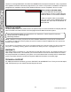
INTRODUCTION Thanks for choosing MB QUART! The RZR-Tuned MBQR-POD-2 kick panel-mounted 8” 2-way compression horn speakers have been meticulously engineered for your vehicle. The process of installation is simple and straightforward. Installation following these detailed instructions can be completed in about 1.5 hours.
INSTALLATION TIME About 1.5 hours are required to complete this installation, not including other system components. ● Blue Painter’s Tape and Marker Pen ● Small (Jeweler’s) Screwdriver ● Bojo Tools (Pry Tools) ● Socket (preferably deep) ● 1/2” Open Box Wrench ● T40 Torx Driver Depending on which vehicle-specific RZR-Tuned audio system you are installing and what other components (not included in this kit) that are also being installed, you may or may not need all of the tools listed below.
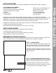
WHAT FITS MY VEHICLE? TWO RZR-TUNED SOURCE UNIT OPTIONS! Depending on whether or not your RZR® vehicle has the optional Ride Command® system, you can purchase optional MB Quart source unit options to suit your application. ABOUT RIDE COMMAND® All Polaris® RZR® vehicles up to 2017 do not have the Ride Command. It wasn’t available as an option. From the 2017 RZR XP® 1000 EPS Velocity Blue Limited Edition and later RZR model years, you can have Ride Command as an option.
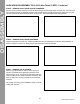
DASH AREA DISASSEMBLY 2013-2018 (Non-Turbo S) RZR Please note, separate disassembly instructions for the 2018.5 Turbo S and 2019+ RZR models are found on pages 7-9 in this manual. Figure 5-1 STEP 2 - REMOVE TOP OF DASH Remove (2) T40 screws as shown in Figure 5-2. Slide dash forward to access back of dash and unplug gauges and switches one at a time. Set dash aside in a safe location. This will provide wiring access.
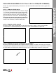
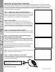
DISASSEMBLY DASH AREA DISASSEMBLY 2013-2018 (Non-Turbo S) RZR - Continued STEP 5 – REMOVE DASH FASCIA CENTER HARDWARE Remove (4) Torx screws from the front of the dash through the openings shown in Figure 5-6. The first set of Torx screws will come out allowing access to the second (upper) set further back in the dash. Next, pull the only the center of the dash loose as shown in Figure 5-7. This will provide further wiring access.
DASH AREA DISASSEMBLY 2018.5 Turbo S & 2019+ RZR (RIDE COMMAND) STEP 1 – REMOVE CENTER HOOD Remove the center of the hood area as shown in Figure 7-1. Twist the recessed tabs at the upper left and right corners. Pull up to remove. Next, pull passenger’s side grab bar retaining clip and pin, then firmly pulling the grip toward the rear of the vehicle. This is where you will access the bus bar if you will also be installing an amplifier to power the kick panel speakers.
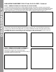
DISASSEMBLY DASH AREA DISASSEMBLY 2018.5 Turbo S & 2019+ RZR - Continued STEP 4 – REMOVE DYNAMIX® ECU BRACKET OR POCKET SCREW If no Ride Command, Dynamix ECU or OEM installed amplifier are present, proceed to removing lower pocket. If you have the Dynamix ECU or OEM installed amplifier, remove (4) 10mm bolts holding the bracket as shown in Figure 7-4a. Move the ECU and/or OEM amplifier to the side leaving wire connections intact.
DASH AREA DISASSEMBLY 2018.5 Turbo S & 2019+ RZR - Continued Figure 7-7a Figure 7-7b STEP 8– REMOVE DASH FASCIA Gently pull dash fascia toward seat to remove as shown in Figure 7-8. Set aside in a safe location until it’s time for reassembly. This allows further access for running wires. Figure 7-8 STEP 9 – REMOVE THE GLOVE BOX Remove (2) 10mm bolts on the top of the glove box where it is fastened to the grab bar framework. See holes in Figure 7-9. The glove box will easily slide out.
KICK PANEL SPEAKERS MOUNTING THE KICK PANEL SPEAKERS Through hundreds of installations, we’ve found once mounting holes are drilled, it’s best to start with the driver’s side kick panel and then move on to the passenger’s side kick panel to complete the mounting and wiring of the kick panels. This way you only need the drill out once, then completely finish the left before moving on to the right.
MOUNTING THE KICK PANEL SPEAKERS (Continued) STEP 7 – PUSH OUTER BOLTS THROUGH FENDER AND MOUNT DRIVER’S SIDE KICK PANEL With the included hardware push (1) bolt and (1) washer through the inner passenger side fender well into the threaded insert of the driver’s side kick panel pod. This leaves only the head of the bolt visible behind the tire.
INITIAL TESTING INITIAL TESTING This step is to confirm that everything is working before you put the vehicle back together. STEP 1 – RECONNECT THE BATTERY With the kick panel speakers wired to your amplifier, you can now reconnect the negative terminal of the negative battery cable as indicated in Figure 19-1. Figure 19-1 STEP 2 – TURN ON IGNITION Turn the ignition key to the ACC position and push the PWR button on your source unit.
VEHICLE REASSEMBLY Follow along the dual amplifier audio harness and zip-tie the harness to the vehicle to assure it doesn’t come loose during rides. Do not zip-tie the harness to any heat or moisture sources. 2013-2018 RZR Models ● TIGHTEN NEGATIVE BATTERY TERMINAL FULLY ● REINSTALL SEATS ● ZIP-TIE ALL WIRING WHILE AVOIDING HEAT SOURCES OR MOVING PARTS ● REASSEMBLE AND FINALIZE ANY OTHER AUDIO SYSTEM COMPONENTS YOU INSTALLED ● REASSEMBLE TOP OF DASH ● REPLACE HOOD 2018.
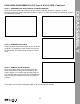
COMPLETE WIRING LAYOUT WIRING LAYOUT This is a complete wiring harness layout diagram of a RZR Stage 5 system. Your kick panels are only one part of the whole audio system package possible. Part#MBQR-POD-2 Shown To view all the RZR-Tuned Audio System Options, visit MBQuart.com 14 ©2020 Maxxsonics USA, Inc.
NOTES Use this section to record serial numbers of each product, final gain and crossover settings of amplifiers or any other wiring or installation-related details that will be helpful if you need to add on to the system or troubleshoot any unforeseen issues.
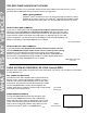
FCC Notice This equipment has been tested and found to comply with the limits for a Class B digital device, pursuant to part 15 of the FCC Rules. These limits are designed to provide reasonable protection against harmful interference in a mobile installation. This equipment generates, uses and can radiate radio frequency energy and, if not installed and used in accordance with the instructions, may cause harmful interference to radio communications.
® MUSIC. DEFINED. MBQR-POD-2 STAGE 2 UTV-Tuned Audio Please visit https://mbquart. com/product-manuals or use your smartphone's camera to capture the QR code to download or view the complete MBQR-POD-2 installation instructions. • I!]. https://mbquart.com/product-manuals © 2020 Maxxsonics USA, Inc. Rev 1.
® MUSIC. DEFINED. Quick Start Installation Guide NA2-400.2RC NA2-320.4 NA2-400.1 NA2-500.5 Congratulations on your choice of a MBQuart amplifier. This "Quick Start Installation" guide is meant to help you "hook up" and play music. For more detailed information, on system setting, speaker and subwoofer configuration and full specifications by model visit the website, http://mbquart.com/manuals.
Before you start /! ·. · CAUTION /! ·,, Marly new andJac:;tory_radios require ·a reset code when disconr.iected from battery power. This is an anti-theft featur~,/Before unplugging power, you must determine if your.radio/source unit requires a reset code. Cfieck the operation 1mcu1Ual for your vehicle or contact . the dealer . . . ..... . ,• · . -~---•~ ....... ..!!...: _ _._ •. - . •.. :.. - Power cable size and fusing It is critical to use the proper power and ground cable.
9·, Chassis Groun'! .. ' _· • ~ . - . , , - ■ -~I• I-•' I I : I .. ...! _• 4 , .• r, - • ----~ • The chassis ground connection is critical to the performance of the amplifier. Choose a location that is close to the amplifier. Completely scrape away the paint and use a nut and bolt if possible. DO NOT USE AN EXISTING FACTORY BOLT! . 0 ,,Power,.·- ---=-- ~-•..:,,._T.£~--•-,., ..r 1 : 1 • ••• I : - . - • . Attach the chassis ground, +12V and remote wire.
- E) Speaker Connections · - ' Connect the speaker cables to the speaker output connectors. Follow the diagram below that best fits your speaker configuration. NA2-400.1 / NA2-500.5 Speaker Positive - Gray Speaker Negative - Gray I Black NA2-400 .2RC Left Positive - White Left Negative - White / Black Right Positive - Gray Right Negative - Gray I Black NA2-320.4 / NA2-500.
Setup The illustrations below describe the various controls. Refer to the illustration that matches your amplifier. , -- ---- - - --- --- eoosr----® ' NA2-400.1 1 I c:111 Odl G) GAIN Adjustment The gain control purpose is to match the output of your source signal to the amplifier. Refer to the section B below for detailed instructions. 0 X-OVER Switch '@JI I I LEVEL LPF SUBSOHK: I ® ®@ • J'z, 7·-7-: G5 @ © ; '------- - - - --- NA2-400.2RC : ~ .. .
Remote Level Control Some models include a bass remote. Avoid adjusting the bass remote while operating vehicle. CJ@ M BOuart.corr1 #MUSIC DEFINED The information contained within this document is intended to offer some basic guidelines for a few of the most common installations. More complex audio systems should be installed by a competent professional. Additional installation information available at www.maxxsonics.com WARRANTY Maxxsonics USA Inc.