
Owner's Manual
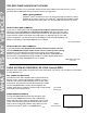

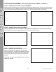
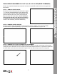
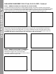
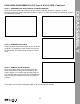
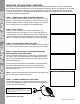
Table Of Contents

10
©2020 Maxxsonics USA, Inc.
MOUNTING THE KICK PANEL SPEAKERS
Through hundreds of installations, we’ve found once mounting holes are drilled, it’s best to start with the
driver’s side kick panel and then move on to the passenger’s side kick panel to complete the mounting and
wiring of the kick panels. This way you only need the drill out once, then completely nish the left before
moving on to the right. The subwoofer should already be mounted at this stage and both kick panel wires
run to their respective general areas.
STEP 1 – MARK HOLES USING SUPPLIED TEMPLATE
Use a few small lengths of painter’s tape in the kick panel area to
easily see marks left by a felt-tipped pen or pencil. Place the clear
plastic template on driver’s side as shown in Figure 14-1 and mark
the mounting holes to drill. Repeat on the passenger side.
STEP 2 – DRILL HOLES
Drill (2) 1/2 inch mounting holes into the fender where you
marked the tape shown in Figure 14-2. A 1/2 inch step drill bit is
recommended for this step. Repeat this process and drill two more
1/2 inch mounting holes on the passenger’s side kick panel area.
Remove any tape in the drilling area from the interior kick panels.
STEP 3 - PLACE DRIVER’S SIDE KICK PANEL
Place driver’s side kick panel pod in its location as shown in Figure
14-3. Ensure the positioning lines up with the holes you’ve drilled.
STEP 4 – PUSH OUTER BOLTS THROUGH FENDER AND
MOUNT DRIVER’S SIDE KICK PANEL
With the included hardware push (1) bolt and (1) washer through
the driver’s side inner fender well into the threaded insert of the
driver’s side kick panel pod. This leaves only the head of the bolt
visible behind the tire.
Once the rst bolt and washer are threaded in, insert and thread
the second bolt and washer for a total of two bolts/washers
attaching the kick panel pod to the driver’s side fender well as
shown in Figure 14-4.
NOTE - Wait to mount passenger side kick panel until driver’s side
panel is completely mounted and wired.
STEP 5 – CONNECT WIRING INTO KICK PANEL
Connect wiring from your amplier to the wire harness from the
kick panel as indicated. Route the wire away from moving parts or
sources of moisture and heat.
(Continued on next page)
Figure 14-1
Figure 14-2
Figure 14-3
Figure 14-4
Thread bolts/washers into kick panel pod
● SOLID WHITE - Left Front Speaker +
● WHITE/BLACK - Left Front Speaker -
● RED - Illumination + (Optional LED Light Ring Required)
● BLACK - Illumination -
KICK PANEL SPEAKERS