Installation Manual MBQR-SUB-2 10” Subwoofer / 400 Watt RZR-Tuned Audio Package for Polaris® RZR® Vehicles
INTRODUCTION Thanks for choosing MB QUART! The RZR-Tuned MBQR-SUB-2 Subwoofer Kit has been meticulously engineered for your vehicle. The process of installation is simple and straightforward. Installation following these detailed instructions can be completed in about 2 hours. INSTALLATION OVERVIEW VIDEO Many of the MB Quart vehicle-specific products feature a “how to” install video with additional details on a successful installation Locate your specific video on the website.
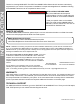
INSTALLATION TIME About 2 hours are required to complete this installation assuming you already have an existing Stage 2 installation completed - either MBQR-STG2-RAD-2 or MBQR-STG2-RC-1. ● Bojo Tools (Pry Tools) ● Small (Jeweler’s) Screwdriver ● Socket (preferably deep) ● 1/2” Open Box Wrench ● T40 Torx Driver Depending on which vehicle-specific RZR-Tuned audio system you are installing, you may or may not need all of the tools listed below.
WHAT FITS MY VEHICLE? TWO RZR-TUNED AUDIO SYSTEM OPTIONS: ENHANCE YOUR SUBWOOFER! The Stage 2 audio system compliments your MBQR-SUB-2 subwoofer installation perfectly! Depending on whether or not your RZR® vehicle has the optional Ride Command® system, you have two choices. This also provides amplifier mounting plates and a fully integrated wiring harness to make the subwoofer installation seamlessly integrated. The Stage 2 system would be purchased separately.
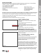
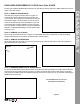
DASH AREA DISASSEMBLY 2013-2018 (Non-Turbo S) RZR Figure 5-1 STEP 1 – REMOVE CENTER HOOD Start with removing the hood as shown in Figure 5-1. Twist the tabs at the upper left and right corners. Pull up to remove. This is where you will access the bus bar described on page 3 of this manual. Confirm that your machine has the bus bar harness installed. If your bus bar harness has not been installed, you can purchase from your dealer or Polaris online.
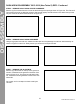
DISASSEMBLY DASH AREA DISASSEMBLY 2013-2018 (Non-Turbo S) RZR - Continued STEP 5 – REMOVE DASH FASCIA CENTER HARDWARE Remove (4) Torx screws from the front of the dash through the openings shown in Figure 5-6. The first set of Torx screws will come out allowing access to the second (upper) set further back in the dash. Next, pull the only the center of the dash loose as shown in Figure 5-7.
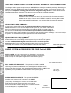
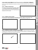
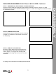
DASH AREA DISASSEMBLY 2018.5 Turbo S & 2019+ RZR (RIDE COMMAND) STEP 1 – REMOVE CENTER HOOD Remove the center of the hood area as shown in Figure 7-1. Twist the recessed tabs at the upper left and right corners. Pull up to remove. Next, pull passenger’s side grab bar retaining clip and pin, then firmly pulling the grip toward the rear of the vehicle.
DISASSEMBLY DASH AREA DISASSEMBLY 2018.5 Turbo S & 2019+ RZR - Continued STEP 4 – REMOVE DYNAMIX® ECU BRACKET OR POCKET SCREW If no Ride Command, Dynamix ECU or OEM installed amplifier are present, proceed to removing lower pocket. If you have the Dynamix ECU or OEM installed amplifier, remove (4) 10mm bolts holding the bracket as shown in Figure 7-4a. Move the ECU and/or OEM amplifier to the side leaving wire connections intact.
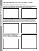
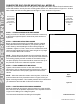
DASH AREA DISASSEMBLY 2018.5 Turbo S & 2019+ RZR - Continued Figure 7-7a Figure 7-7b STEP 8– REMOVE DASH FASCIA Gently pull dash fascia toward seat to remove as shown in Figure 7-8. Set aside in a safe location until it’s time for reassembly. Figure 7-8 STEP 9 – REMOVE THE GLOVE BOX Remove (2) 10mm bolts on the top of the glove box where it is fastened to the grab bar framework. See holes in Figure 7-9. The glove box will easily slide out. A different mounting method is used for the new subwoofer.
SUBWOOFER MOUNTING SUBWOOFER ENCLOSURE MOUNTING (ALL MODELS) Prepare to mount the subwoofer into the glove box and grab bar location. 2018.5 Turbo S and 2019 and newer RZR models, use only the rear mounting plate and four 1/2” bolts as shown in Figure 8-1. All other RZR models use both mounting plates and all eight 1/2” bolts as shown in Figure 8-2. 2018.5 Turbo S and 2019+ RZR Models use only rear mounting plate and four 1/2” bolts.
AMPLIFIER WIRING If you are connecting the amplifier on its own please refer to the electrical connections outlined in the NA2-400.1 installation manual available at MBQuart.com. Figure 9-1 It’s recommended that you connect the amplifier’s power and ground wiring at the RZR bus bar location as described on page 3. Use at least 10 AWG power and ground wire. Be sure to fuse the amplifier’s main power wire with a 30 ampere fuse placed close to the point of connection at the bus bar.
INITIAL TESTING INITIAL TESTING This step is to confirm that everything is working before you put the vehicle back together. STEP 1 – RECONNECT THE BATTERY With the power/ground wiring connected to the bus bar, reconnect the negative terminal of the negative battery cable as indicated in Figure 10-1. Figure 10-1 STEP 2 – TURN ON IGNITION Turn the ignition key to the ACC position and push the PWR button on your source unit. STEP 3 – INITIAL CHECKS Confirm connectivity of the system you just installed.
FINE TUNING NOTE – Gain control, it is important to adjust each amplifier gain as described in the manual. Remember, these settings are NOT volume controls. Gain controls, properly adjusted help properly balance the system sound between lows, highs and minimize distortion that comes from the source unit. Listen for a clear, crisp audio sound. The ideal gain setting should allow full volume from the source unit without audible distortion. A The illustrations below describe the various controls.
REASSEMBLY VEHICLE REASSEMBLY Follow along any wiring you’ve routed and zip-tie to the vehicle to assure it doesn’t come loose during rides. Do not zip-tie your wiring to any heat or moisture sources. Once your wiring is secure, you can begin reassembling all the panels.
FINAL INSPECTION Here is a checklist to make sure your vehicle is ready to hit the trails. You should pull & tighten everything so that you know your RZR and your audio equipment are secure. *NOTE – It is critical to the safe operation of your vehicle that the nuts holding the steering column in 20132018 models be re-tightened to 40-foot pounds of torque.
WIRING LAYOUT COMPLETE WIRING LAYOUT This is a complete wiring harness layout diagram of a RZR Stage 5 system. Your subwoofer is only one part of the whole audio system package possible. Subwoofer and Mono Amplifier Kit (part#MBQR-SUB-2) Shown To view all the RZR-Tuned Audio System Options, visit MBQuart.com 16 ©2020 Maxxsonics USA, Inc.
NOTES Use this section to record serial numbers of each product, final gain and crossover settings of amplifiers or any other wiring or installation-related details that will be helpful if you need to add on to the system or troubleshoot any unforeseen issues.
FCC Notice This equipment has been tested and found to comply with the limits for a Class B digital device, pursuant to part 15 of the FCC Rules. These limits are designed to provide reasonable protection against harmful interference in a mobile installation. This equipment generates, uses and can radiate radio frequency energy and, if not installed and used in accordance with the instructions, may cause harmful interference to radio communications.