OPERATOR’S SAFETY AND SERVICE MANUAL AIRAMMER This manual covers the following serial numbers and higher for each model listed: AR56/AR57 . . . . . . . . . . . . . . . . 570059 RAMMERS MBW, Inc. MBW (UK) Ltd. MBW France S.A.R.L 250 Hartford Rd • PO Box 440 Slinger, WI 53086-0440 Phone: (262) 644-5234 Fax: (262) 644-5169 Email: mbw@mbw.com Website: www.mbw.com Units 2 and 3 Cochrane st Bolton BL3 6BN, England Phone: 44 (0) 01204 387784 Fax: 44 (0) 01204 387797 Z.A.
TABLE OF CONTENTS Safety Information . . . . . . . . . . . . . . . . . . . . . . 1 Introduction . . . . . . . . . . . . . . . . . . . . . . . . . . . . . . . . . 1 Safety Precautions . . . . . . . . . . . . . . . . . . . . . . . . . . . 1 Safety Decals . . . . . . . . . . . . . . . . . . . . . . . . . . . . . . . 1 Motor Removal . . . . . . . . . . . . . . . . . . . . . . . . . . . . . . 7 Pinion Removal . . . . . . . . . . . . . . . . . . . . . . . . . . . . . 7 Gearbox Removal . . . . . . . . . . . . . .
This page intentionally left blank.
SAFETY INFORMATION Introduction SAFE DRESS: Do not wear loose clothing, rings, wristwatches, etc. near machinery. This Safety Alert Symbol is used to call attention to items or operations which may be dangerous to those operating or working with this equipment. The symbol can be found throughout this manual and on the unit. Please read these warnings and cautions, along with all decals, carefully before attempting to operate the unit.
CAUTION 13538 Machine is top heavy and could fall if not lifted from this bar. AIRAMMER= #120 (54kg) 17779 17779 13535 19789 (not in decal set) CAUTION !"$ %&''*+ - % 8& : ! &! $ -! ;* % !$ 6! -" Read the Operating Instructions before operating this piece of equipment.
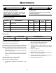
SPECIFICATIONS AR56 AR56 AR57 Operating Weight 123 lbs (56 kg) 125 lbs (57 kg) Percussion Rate 650 blows/minute 650 blows/minute Shoe Size 11” x 13” (28 cm x 33cm) 13” x 15” (33 cm x 38 cm) Travel Speed 60 ft/min (18.3 m/min) 60 ft/min (18.
OPERATION Introduction Connecting to Air Compressor MBW equipment is intended for use in very severe applications. The Airammer is powered by a pneumatic motor and is available with different size tamping shoes. For proper operation, the Airammer requires a compressed air supply of at least 75 cfm at 110 psi. This parts manual contains only standard parts. Variations of these parts as well as other special parts are not included.
Stopping Airammer 1. Release Airammer actuator handle. 2. Close compressor valve to release supply pressure to the Airammer. 3. Squeeze the actuator handle to relieve all residual air pressure in the hose. 4. Disconnect the air hose from the Airammer. WARNING Always stop the motor and disconnect the air supply before: Leaving the equipment unattended for any amount of time. Before making any repairs or adjustments to the machine.
MAINTENANCE WARNING CAUTION Always exercise the stopping procedure before servicing or lubricating the unit. Always verify fluid levels and check for leaks after changing fluids. After servicing the unit, replace and fasten all guards, shields, and covers to their original positions before resuming operation. Do not drain oil onto ground, into open streams, or down sewage drains.
SERVICE Assembly and disassembly should be performed by a service technician who has been factory trained on MBW equipment. The unit should be clean and free of debris. Pressure washing before disassembly is recommended. Service Tools 01629 Rubber Test Mat • Prior to assembly, wash all parts in a suitable cleaner or solvent. 20260 Springbox Tool 07205 Bellows Installation tool 07552 Blind Hole Bearing Puller Tool Part No. • Check moving parts for wear and failure.
Gearbox Removal It is necessary to remove the handle and motor to remove the gearbox. Refer to Gearbox Assembly, page 14. 1. Remove the four socket head cap screws (#35) and lockwashers (#21) securing the gearbox (#25) to the guide tube (#17, page 16). 2. Compress the bellows enough to insert a small wooden block between the gearbox (#25) and the guide tube (#17, page 16). 3.
10. Use a blind hole bearing puller to remove the two needle bearings (#11 and #12) from the cover. Breather Removal Refer to Gearbox Assembly, page 14. 1. Remove the socket pipe plug (#29) from the top of the breather assembly. 2. Remove spring (#19), washer (#28), and valve (#18). 6. While holding the bottom of the rods from turning, slowly and evenly back off the nuts on the cover side. 7. After the tension is removed from the cover, the springbox tools and the cover can be removed. 8.
6. Press the crank gear into the cover. Place a snap ring pliers through the slot in the crank gear and secure the retaining ring (#15). WARNING Working with compressed springs. Failure to follow the next set of steps very carefully could result in serious injury or death. Pinion Assembly Refer to Gearbox Assembly, page 14. 9. 1. Use the wrench flats on the pinion (#27) to thread the it onto the motor (#22). 2.
5. Secure the gearbox to the guide tube using four socket head cap screws (#35) and high collar lockwashers (#21). Apply 243 Loctite. Handle Assembly Refer to Handle Assembly, page 18. 1. Secure the handle (#7) to the shockmounts (#8) using four whiz-lock screws (#11). 2. Reattach the hose (#3) to the motor (#22, page 14) and secure with two new clamps (#9). Part Replacement Cycles and Tolerances Bearings Replace anytime a bearing is rough, binding, discolored or removed from housing or shaft.
This page intentionally left blank.
REPLACEMENT PARTS The warranty is stated in this book on page 18. Failure to return the Warranty Registration Card renders the warranty null and void. MBW has established a network of reputable distributors/ dealers with trained mechanics and full facilities for maintenance and rebuilding, and to carry an adequate parts stock in all areas of the country. Their sales engineers are available for professional consultation.
Gearbox Assembly - 14 -
ITEM 1. 2. 3. 4. 5. 6. 7. 8. 9. 10. 11. 12. 13. 14. 15. 16. 17. 18. 19. 20. 21. 22. 23. 24. 25. 26. 27. 28. 29. 30. 31. 32. 33. 34. 35. PART NO. 01001 01002 01072 01103 01105 01191 05559 06161 06238 06240 06259 06260 06264 06265 06266 06275 06304 06413 06423 06925 08504 12189 15768 19708 19754 19779 19782 F01PW F0418SPP F042008FWS F042014FSS F051808FWS F0618SPP F081305HCS F081312SCS DESCRIPTION RETAINING RING, EXT.
Lower Unit Assembly - 16 -
ITEM 1. 2. 3. 4. 5. 6. 7. 8. 9. 10. 11. 12. 13. 14. 15. 16. 17. 18. 19. 20. 21. 22. 23. 24. PART NO. 03167 03168 06173 06174 06180 06237 06257 07154 07163 07735 11694 18276 07507 03172 19728 19763 19889 19890 19891 19893 F0227SPP F042005FSS F042008HCS F04LW F071412HCS F07LW DESCRIPTION SPRING, COMPRESSION, 2.188” OD SPRING, COMPRESSION, 2.875” OD COVER RAM BEARING, SLIDE O-RING, 4.
13 5 10 4 12 6 14 7 4 13 2 9 11 3 8 9 11 1 Handle Assembly - 18 -
ITEM 1. 2. 3. 4. 5. 6. 7. 8. 9. 10. 11. 12. 13. 14. PART NO. 19631 19711 19713 19718 19719 19720 19721 19726 19805 F051804FWS F051808FWS F061605FWS F061610HCS F0616FN DESCRIPTION SHROUD, AIRAMMER VALVE ASM, AIRAMMER HOSE, 3/4 AIR BUSHING, BRONZE ACORN NUT, 5/16-18 TRIGGER, COATED HANDLE, COATED SHOCKMOUNT ASM, AIRAMMER CLAMP, PINCH, 1.00-1.
Valve Assembly - 20 -
ITEM 1. 2. 3. 4. 5. 6. 7. 8. 9. 10. 11. 12. 13. 14. 15. 16. 17. PART NO. 01177 03810 03812 12251 19705 19706 19707 19708 19709 19710 19713 19714 19715 19716 19717 19805 F042012SCS DESCRIPTION FITTING, GREASE STD SEAL, VALVE PIN SPRING, COMPRESSION, .720 OD FITTING, COUPLER, DIXON AM-7 VALVE, BODY BALL, CHROME, 1” PUSH PIN FITTING, ST, 1/2 NPT X 3/4” HOSE VALVE, END WITH SWIVEL SWIVEL, 3/4 HOSE HOSE, 3/4 AIR RETAINING RING, INT. 11/16 ORING, 1.75 ID, X .0625 DIA BALL, CHROME, 3/16 ORING, .563 ID, .
WARRANTY- AIRAMMER (AR56/AR57) WHAT DOES THIS WARRANTY COVER? MBW, Incorporated (MBW) warrants each New Machine against defects in material and workmanship for a period of thirty six (36) months. "New Machine" means a machine shipped directly from MBW or authorized MBW dealer to the end user. This warranty commences on the first day the machine is sold, assigned to a rental fleet, or otherwise put to first use. batteries, and the like, all of which are sold AS IS/WHERE IS WITH ALL FAULTS.