OPERATOR’S SAFETY AND SERVICE MANUAL GP12, GP15, GP18 This manual covers the following serial numbers and higher for each model listed: GP12........................................................1120500 GP15........................................................1160172 GP18........................................................1180312 VIBRATORY PLATES MBW, Inc. MBW (UK) Ltd. 250 Hartford Rd • PO Box 440 Slinger, WI 53086-0440 Phone: (262) 644-5234 Fax: (262) 644-5169 Email: mbw@mbw.com Website: www.
TABLE OF CONTENTS Safety Information . . . . . . . . . . . . . . . . . . . . . . 1 Engine Maintenance. . . . . . . . . . . . . . . . . . . . . . . . . . 7 Introduction . . . . . . . . . . . . . . . . . . . . . . . . . . . . . . . . . 1 Engine RPM . . . . . . . . . . . . . . . . . . . . . . . . . . . . . . . . 7 Safety Precautions . . . . . . . . . . . . . . . . . . . . . . . . . . . 1 Safety Decals . . . . . . . . . . . . . . . . . . . . . . . . . . . . . . . 1 Changing Exciter Oil. . . . . . . . . . .
WARNING CALIFORNIA PROPOSITION 65 WARNING Engine exhaust and some of its constituents are known in the state of California to cause cancer, birth defects, and other reproductive harm.
SAFETY INFORMATION Introduction SAFE DRESS: Do not wear loose clothing, rings, wristwatches, etc. near machinery. This Safety Alert Symbol is used to call attention to items or operations which may be dangerous to those operating or working with this equipment. The symbol can be found throughout this manual and on the unit. Please read these warnings and cautions, along with all decals, carefully before attempting to operate the unit.
WARNING OPERATION OF THIS EQUIPMENT MAY CREATE SPARKS THAT CAN START FIRES AROUND DRY VEGETATION. A SPARK ARRESTER MAY BE REQUIRED. THE OPERATOR SHOULD CONTACT LOCAL FIRE AGENCIES FOR LAWS OR REGULATIONS 19791 RELATING TO FIRE PREVENTION 19791 12500 WARNING ROTATING PARTS can crush and cut.
SPECIFICATIONS AP12 CENTRIFUGAL FORCE GP12 AP15 GP15 AP18 1920 lbs (873 kg) 1920 lbs (873 kg) 2000 lbs (898 kg) 2000 lbs (898 kg) 2780 lbs (1261kg) GP18 2780 lbs (1261kg) EXCITER (VPM) 5240 5240 5350 5350 5240 5240 TRAVEL SPEED 83ft./min. (25m/min.) 83ft./min. (25m/min.) 68ft./min. (21m/min.) 68ft./min. (21m/min.) 75ft./min. (23m/min.) 75ft./min. (23m/min.) 10 in. (25 cm) 10 in. (25 cm) 10 in. (25 cm) 10 in. (25 cm) 10 in. (25 cm) 10 in. (25 cm) 13 x 22.5 in.
OPERATION Introduction Starting Engine MBW equipment is intended for use in very severe applications. They are powered by four cycle engines and are available in different sizes and a selection of engines. This parts manual contains only standard parts. Variations of these parts as well as other special parts are not included. Contact your local MBW distributor for assistance in identifying parts not included in this manual.
WARNING Always stop the engine before: Adding fuel. Leaving the equipment unattended for any amount of time. Before making any repairs or adjustments to the machine.
MAINTENANCE WARNING CAUTION Always exercise the stopping procedure before servicing or lubricating the unit. Always verify fluid levels and check for leaks after changing fluids. After servicing the unit, replace and fasten all guards, shields, and covers to their original positions before resuming operation. Do not drain oil onto ground, into open streams, or down sewage drains.
SERVICE Assembly and disassembly should be performed by a service technician who has been factory trained on MBW equipment. The unit should be clean and free of debris. Pressure washing before disassembly is recommended. Service Tools 01629 Test Mat • Prior to assembly, wash all parts in a suitable cleaner or solvent. 12100 Decal Set Part No. Engine Maintenance • Check moving parts for wear and failure. Refer to the Replacement section in this manual for tolerance and replacement cycles. 1.
Belt Adjustment Refer to MAIN ASSEMBLY, page 14. 1. Remove hardware(13) securing painted belt guard (10) to engine deck and remove belt guard(10). Remove plastic belt guard (7) for full access to belt. 2. Apply moderate thumb pressure to belt about half way between pulleys. When properly adjusted the belt should deflect approximately 3/8” (9mm). If the belt is adjusted correctly reinstall belt guard and hardware. 3. To adjust belt tension loosen (4) screws securing engine to engine deck. 4.
13. Install shaft key and slide pulley onto exciter shaft. Apply medium strength loctite to the set screw and make sure the exciter shaft turns freely. 14. Fill exciter housing with oil as described in Changing Exciter Oil section of this manual. Parts Replacement Cycles and Tolerances Bearings Replace anytime a bearing is rough, binding, discolored or removed from housing or shaft. Clutch Replace clutch if it does not disengage below 1800 rpm.
REPLACEMENT PARTS The warranty is stated in this book on page 20. Failure to return the Warranty Registration Card renders the warranty null and void. MBW has established a network of reputable distributors/ dealers with trained mechanics and full facilities for maintenance and rebuilding, and to carry an adequate parts stock in all areas of the country. Their sales engineers are available for professional consultation.
This page intentionally left blank.
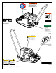
EXCITER ASSEMBLY - 12 -
ITEM 1. 2. 3. 4. 5. 6. 7. 8. 9. 10. 11. 12. 13. 14. 15. 16. PART NO. 01072 01191 17179 20379 06335 19630 20751 20408 20533 20538 20756 20536 20757 20758 20760 16395 20776 F0227SPP F042007FWS F051804SSS DESCRIPTION FILTER, FELT RETAINING RING, INTERNAL SEAL, SHAFT, 1.25” SEAL, SHAFT, 1.25” (VITON) GP18 ONLY KEY, 1/4 SQ X 1” LG PULLEY, EXCITER, 1.0 X 3.88 BOTTOM PLATE WELDMENT BOTTOM PLATE WELDMENT BOTTOM PLATE WELDMENT RETAINING RING, INT. 3.
MAIN ASSEMBLY - 14 -
ITEM 1. 2. 3. 4. 5. 6. 7. 8. 9. 10. 11. 12. 13. 14. 15. 16. 17. 18. 19. 20. 21. 22. 23. 24. 25. 26. 27. 28. PART NO. 00032 01289 12860 17210 20382 14993 16105 16908 20759 20768 20426 20530 20771 20772 20773 20789 20793 20795 F042005TCS F051807FWS F051812HCS F052406FSS F052406HCS F05LW F05SW F0518ELN F081306BCS F081306HCS F081308HCS F08LW F08SW M12ETLW DESCRIPTION KEY, 3/16” SQ. x 1-5/8 LG.
HANDLE ASSEMBLY - 16 -
ITEM 1. 2. 3. PART NO. 12767 17643 20537 18515 4. 5. 6. 7. 20763 20796 F042004FWS F0420FN 20435 DESCRIPTION HAIR PIN, 3/32 DIA. SHOCKMOUNT SNUBBER, 1” DIA. SNUBBER, For Serial Numbers: GP12-1120500, GP15-1160172 and GP18-1180312 and lower HANDLE, ASSEMBLY (INCLUDES ITEM #1) HANDLE BRACKET, PLATE FWLS, 1/4-20x1/2 ZP FLANGE WHIZ-LOCK NUT, 1/4-20 SERVICE KIT, HONDA PLATE, INCLUDES: (4) #16908 SHOCK MOUNT (4) #17643 SHOCK MOUNT (HANDLE) (2) #20537 SNUBBER 1” DIA.
OPTIONAL EQUIPMENT - 18 -
ITEM PART NO. DESCRIPTION QTY WATER TANK 1. 2. 3. 4. 5. 6. 7. 8. 9. 10. 11. 12. 13. 05803 06192 08442 17643 20486 20489 20490 20491 20492 20493 20494 20496 20497 F042004FWS F081314BCS PIPE ADAPTER, MALE GROMMET, WATER TANK CLAMP, WORM DRIVE SHOCK MOUNT 1” DIA. WATER TANK, GPX PLATE SPRAY BAR, AP12 SPRAY BAR, AP15 SPRAY BAR, AP18 CAP, SQ. TUBE SEALING WASHER HOSE, 1/4” x 7” LG. CAP, WATER TANK VALVE, WATER TANK FLANGE HEAD SCREW, 1/4-20 x 1/2 LG. BUTTON HEAD SCREW, 1/2-13 x 1-3/4 LG.
WARRANTY WHAT DOES THIS WARRANTY COVER? MBW, Incorporated (MBW) warrants each New Machine against defects in material and workmanship for a period of twelve (12) months. "New Machine" means a machine shipped directly from MBW or authorized MBW dealer to the end user. This warranty commences on the first day the machine is sold, assigned to a rental fleet, or otherwise put to first use. MBW warrants each Demonstration Machine against defects in material and workmanship for a period of six (6) months.
NOTES: 21
NOTES: 22