OPERATOR’S SAFETY AND SERVICE MANUAL GPR99 & GPR135 This manual covers the following serial numbers and higher for each model listed: GPR99.......................................3090201 GPR135DE................................2900253 GPR135H...................................2910050 VIBRATOY PLATES MBW, Inc. 250 Hartford Rd • PO Box 440 Slinger, WI 53086-0440 Phone: (262) 644-5234 Fax: (262) 644-5169 Email: mbw@mbw.com Website: www.mbw.com MBW (UK) Ltd. MBW FRANCE S.A.R.L.
TABLE OF CONTENTS Safety Information . . . . . . . . . . . . . . . . . . . . . . 1 Service. . . . . . . . . . . . . . . . . . . . . . . . . . . . . . . . 9 Introduction . . . . . . . . . . . . . . . . . . . . . . . . . . . . . . . . . 1 Torque Chart . . . . . . . . . . . . . . . . . . . . . . . . . . . . . . . 9 Safety Precautions . . . . . . . . . . . . . . . . . . . . . . . . . . . 1 Service Tools . . . . . . . . . . . . . . . . . . . . . . . . . . . . . . . 9 Safety Decals . . . . . . . . . . . . .
WARNING CALIFORNIA PROPOSITION 65 WARNING Engine exhaust and some of its constituents are known in the state of California to cause cancer, birth defects, and other reproductive harm.
SAFETY INFORMATION Introduction SAFE DRESS: Do not wear loose clothing, rings, wristwatches, etc. near machinery. This Safety Alert Symbol is used to call attention to items or operations which may be dangerous to those operating or working with this equipment. The symbol can be found throughout this manual and on the unit. Please read these warnings and cautions, along with all decals, carefully before attempting to operate the unit.
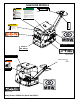
DIESEL MODEL IDLE STOP THROTTLE CAUTION 19493 #19493 Machine may fall and cause injury or damage if lifted improperly. Lift only by lift hook Weight~ #924 (420kg) RUN 15853 #15853 FORWARD REVERSE 14665 #14665 #15847 WARNING CAUTION Read the Operating Instructions before operating this piece of equipment. Keep unauthorized and untrained people away from this equipment. ROTATING & MOVING PARTS! Make sure all guards and safety devices are in place.
GASOLINE MODELS CAUTION Read the Operating Instructions before operating this piece of equipment. Keep unauthorized and untrained people away from this equipment. ROTATING & MOVING PARTS! Make sure all guards and safety devices are in place. Wear approved hearing protection, foot protection, eye protection and head protection. STOP SHUT OFF the motor before servicing or cleaning. DO NOT RUN in an enclosed area. The engine produces carbon monoxide, a POISONOUS GAS.
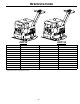
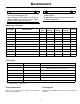
SPECIFICATIONS *53 *53 CENTRIFUGAL FORCE GPR99H GPR135H GPR135DE 9900lbf (44 kN) 13500 lbf (60kN) 13500 lbf (60kN) EXCITER (VPM) 3840 vpm 3840 vpm 3840 vpm TRAVEL SPEED 80 ft./min. (24 m/min.) 78 ft./min. (24 m/min.) 76 ft./min. (23 m/min.) 28 in (71 cm) 28 in (71 cm) 28 in (71 cm) 19.7 x 37.3 in. (50 x 95 cm) 19.7 x 37.3 in. (50 x 95 cm) 19.7 x 37.3 in. (50 x 95 cm) 775 lb. (352 kg) 825 lb. (374 kg) 882 lb.
OPERATION Introduction MBW Inc. equipment is intended for use in very severe applications. They are powered by four cycle engines and are available in different sizes and a selection of engines. The MBW Reversible Plate Compactor is intended to compact various soil types. Recommended soil types include granular soils, gravel/sand mixtures, and semigranular cohesive soils. The MBW Reversible Plate Compactor is not recommended for use in cohesive soils nor for very hard surfaces such as concrete or asphalt.
WARNING Stopping Engine 1. To stop the compactor from traveling forward, return the engine throttle to idle position. 2. Whenever possible, it is recommended to let the engine idle for one or two minutes before stopping. 3. Gas engines: Turn the switch on the engine to “STOP” position. Diesel engines: Move the throttle control to the “STOP” position. 4. Turn off the fuel valve where applicable. Always stop the engine before: Adding fuel. Leaving the equipment unattended, even if only for a minute.
MAINTENANCE WARNING CAUTION Always exercise the stopping procedure before servicing or lubricating the unit. Always verify fluid levels and check for leaks after changing fluids. After servicing the unit, replace and fasten all guards, shields, and covers to their original positions before resuming operation. Do not drain oil onto ground, into open streams, or down sewage drains.
Engine Speed 1. Battery Charging Engine speed is factory set according to the speeds listed in the Specifications section of this manual. Do not tamper with the governor setting. The governor establishes safe operating limits which must not be exceeded. 1. The state of charge in an Odyssey battery can be determined from the following chart: Voltmeter Reading State of Charge 12.84 Volts 100% 2. Refer to the engine Owner’s Manual for procedure on setting operating and idle speeds. 12.
SERVICE Assembly and disassembly should be preformed by a service technician who has been factory trained on MBW equipment. the unit should be clean and free of debris. Pressure washing before disassembly is recommended. • Prior to assembly, wash all parts in a suitable cleaner or solvent. Service Tools • Check moving parts for wear and failure. Refer to the Replacement Section of this manual for tolerances and replacement cycles. Part No.
careful to guide the hydraulic line through the handle assembly and engine deck as the subassemblies are separated to prevent damage to components and personal injury. If further disassembly of the engine deck is required proceed to step 9. If baseplate service is required refer to Baseplate Disassembly Procedure section of this manual. 11. Remove the four hex head capscrews (#29) securing the rollcage to the engine deck and remove the rollcage. Refer to DIESEL ENGINE ASSEMBLY, page 32. 12.
7. 13. Clean and inspect the shift spool (#15) and the hydraulic housing (#16). If equipped, reinstall the bushings and baseplate extension using antisieze lubricant (LOCTITE #767). Lower Hydraulic Seal Replacement 14. Reinstall the bleeder screw(#14) into its port in the hydraulic housing (#16). Refer to LOWER SHAFT ASSEMBLY, page 26. 15. Install the new cylinder gasket (#18), the cylinder cover (#19) and the four flanged capscrews (#21).
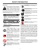
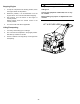
baseplate. Loosen hex head bolts (#32) on the oil drain side only. Lift the engine deck up to allow the hydraulic guard to be removed. Refer to figure 2. 2. Position the handle in the locked position and set the lock pin. 3. Check the hydraulic line (#4) for loose fittings and tighten as needed. 4. Remove the pipe plug (#2) from the control head. 5. Loosen the bleeder screw (#1) located at the hydraulic control housing of the exciter. 6. Fill the control head with hydraulic fluid as shown. 7.
15. Remove the plastic plugs (#1) from the threaded holes in the shaft covers (#7, #9, #12 & #18). This can be done using a #2 phillips screwdriver lightly tapped into the center of the plug and unthreading it as a screw. 16. Clean all dirt from the threaded holes in the shaft covers which were not plugged and “chase” the threads with a 5/16-18 UNC thread tap. 31. Secure the bearings in a vice and press out the shift shaft (#10). Note the position of the spacer washer (#7).
6. Remove the external snap ring (#6) from the pinion shaft (#24). 7. Slide the pinion shaft (#24) out of the control housing(#13). Note the size and location of the O-rings (#4 �) for assembly. 8. Remove the O-rings (#4 & #5) from the pinion shaft (#24). 9. Slide the rack gear (#15), seal (#2) and guide ring (#3) out of the control head housing. Note the orientation of the seal lip. 10. Remove the hex head cap screw (#26) and washer (#31) from the rack gear (#15). 11.
22. Install the other input shaft cover (#12) and secure with the four flange head screws (#22) using LOCTITE #243 thread locker sealant and torque the screws to 13 ft.-lbs. See the figure #3 for LOCTITE #515 gasket maker application. Check input shaft for minimum of .020” end play after covers are installed and the bolts are torqued. 13. Install the 90 degree fitting (#2) containing the roll pin (#20) into the bearing cover (#18) using LOCTITE #565 sealant on the threads.
41. Install the 90 degree fitting (#13) into the port on the hydraulic housing (#16). 29. Align the timing marks on both gears and slide the input gear over the helix pin/carrier and into mesh with the gear on the idler shaft. See the figure #5 for setting the gear timing. 42. Install the bleeder screw (#14) loosely into the port fitting of the hydraulic housing. 30.
Control Head Assembly Procedure Handle Assembly Procedure Refer to HANDLE ASSEMBLY, page 28. Refer to HANDLE ASSEMBLY, page 28. 1. Clean and dry all parts to be assembled. 2. Press the slide bushing (#14) into the control housing (#13). 3. Press the hydraulic seal (#2) onto the rack gear (#15). Be careful to orient the seal lip to face the shaft guide housing (#16). Tip: Use approved hydraulic oil to lubricate the seal inside diameter to ease assembly.
Troubleshooting SYMTOM Engine does not start or stalls. Engine does not accelerate, is hard to start or runs erratically. Engine over heats or runs hot. Engine runs at full speed but machine does not move. Slow or no forward travel speed. REPAIR 1. Fuel valve is closed, open valve (gasoline engine). 2. Engine switch is in “STOP” position, turn switch to “ON” position (gasoline engine). 3. Fouled spark plug, clean or replace spark plug (gasoline engine). 4.
Parts Replacement Cycles and Tolerances Bearings Replace anytime a bearing is rough, binding, discolored or removed from housing or shaft. Clutch Replace clutch if it does not disengage below 1800 rpm. Engine Components Refer to your engine manufacturer’s Owner’s Manual. Hardware Replace any worn or damaged hardware as needed. Replacement hardware should be grade 5 and zinc plated unless otherwise specified. Safety Decals Replace if they become damaged or illegible.
REPLACEMENT PARTS The warranty is stated in this book on page 34. Failure to return the Warranty Registration Card renders the warranty null and void. MBW has established a network of reputable distributors/ dealers with trained mechanics and full facilities for maintenance and rebuilding, and to carry an adequate parts stock in all areas of the country. Their sales engineers are available for professional consultation.
This page intentionally left blank. Contact Information MBW, Inc. MBW (UK) Ltd. MBW FRANCE S.A.R.L. 250 Hartford Rd • PO Box 440 Slinger, WI 53086-0440 Phone: (262) 644-5234 Fax: (262) 644-5169 Email: mbw@mbw.com Website: www.mbw.com Units 2 & 3 Cochrane Street Bolton BL3 6BN, England Phone: 01204 387784 Fax: 01204 387797 Z.A. d’Outreville 11 rue Jean Baptiste Néron, 60540 BORNEL FRANCE Phone: +33 (0) 3 44 07 15 96 Fax: +33 (0) 3 44 07 41 28 Email: mbwfrance@free.
6(( +$1'/( $66(0%/< 3$*( MAIN ASSEMBLY - 22 -
ITEM 1. 2. 3. 4. 5. 6. 7. 8. 9. 10. 11. 12. 13. 14. 15. 16. 17. 18. 19. 20. 21. 22. 23. 24. 25. 26. 27. 28. 29. 30. 31. 32. 33. 34. 35. 36. 37. 38. 39. PART NO.
6(( /2:(5 6+,)7 $66(0%/< 3$*( BASEPLATE ASSEMBLY - 24 -
ITEM 1. 2. 3. 4. 5. 6. 7. 8. 9. 10. 11. 12. 13. 14. 15. 16. 17. 18. 19. 20. 21. 22. 23. 24. 25. 26. PART NO.
LOWER SHAFT ASSEMBLY - 26 -
ITEM 1. 2. 3. 4. 5. 6. 7. 8. 9. 10. 11. 12. 13. 14. 15. 16. 17. 18. 19. 20. 21. 22. PART NO. 05559 16228 16230 16231 16237 16238 16239 16240 16241 16242 16254 16264 16446 17023 17275 17276 17277 17278 17279 17280 F042004FWS F051508FWS 17368 DESCRIPTION CAPPLUG ROLLER BEARING, 100 x 45 BALL BEARING GUIDE RING EXTERNAL RETAINING RING, METRIC HYDRAULIC SEAL WASHER, SHIM INTERNAL RETAINING RING HELIX PIN CARRIER SHIFT SHAFT DOWEL PIN, M10 x 70 BEARING COVER, EXCITER FITTING.
HANDLE ASSEMBLY - 28 -
ITEM 1. 2. 3. 4. 5. 6. 7. 8. 9. 10. 11. 12. 13. 14. 15. 16. 17. 18. 19. 20. 21. 22. 23. 24. 25. 26. 27. 28. 29. 30. 31. 32. 33. 34. 35. PART NO. 08355 16350 16351 16352 16353 16354 16355 16358 16359 16410 19533 16493 16629 16632 16633 16636 17058 17377 17379 17380 17402 17417 17445 17509 17546 F051804HCS F051808FWS F051808SCS F051812FWS F0518FN F05SW F061607FWS F0813HN M08C016FWS M08C025FSS 16638 17369 DESCRIPTION FITTING, STRAIGHT HYDRAULIC SEAL GUIDE RING, HYDRAULIC O-RING, METRIC, 52mm I.D. x 3.
GASOLINE ENGINE ASSEMBLY - 30 -
ITEM 1. 2. 3. 4. 5. 6. 7. 8. 9. 10. 11. 12. 13. 14. 15. PART NO. 00808 07767 12887 09375 16576 16580 16665 16676 16974 17467 F052408FSS F061618HCS F061636SCS F062408FSS F06LW F06PW Q2893907 DESCRIPTION KEY, SQUARE, 1/4 x 1-3/4 HONDA ENGINE, 11 HP, GX340 HONDA ENGINE, 13 HP, GX390 V-BELT, B-44 CLUTCH SPACER, CLUTCH WASHER, MOUNT BELT GUARD HOSE, OIL DRAIN BELT GUARD MOUNT FSS, 5/16-24 x 1, ZP HCS, 3/8-16 x 2-1/4, GR. 5, ZP SCS, 3/8-16 x 4-1/2, GR.
DIESEL ENGINE ASSEMBLY - 32 -
ITEM 1. 2. 3. 4. 5. 6. 7. 8. 9. 10. 11. 12. 13. 14. 15. 16. 17. 18. 19. 20. 21. 22. 23. 24. 25. 26. 27. 28. 29. 30. 31. 32. 33. 34. 35. 36. 37. PART NO.
WARRANTY WHAT DOES THIS WARRANTY COVER? MBW, Incorporated (MBW) warrants each New Machine against defects in material and workmanship for a period of twelve (12) months. "New Machine" means a machine shipped directly from MBW or authorized MBW dealer to the end user. This warranty commences on the first day the machine is sold, assigned to a rental fleet, or otherwise put to first use. batteries, and the like, all of which are sold AS IS/WHERE IS WITH ALL FAULTS.