
Network Hardware User Manual

- 11 -
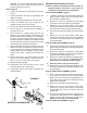
7. If equipped, reinstall the bushings and baseplate
extension using antisieze lubricant (LOCTITE #767).
Lower Hydraulic Seal Replacement
Refer to LOWER SHAFT ASSEMBLY, page 26.
Note: The seals (#6), guide ring (#4), and gaskets (#17
and #18) should be replaced as a set. MBW
recommends purchasing rebuild kit #17368 for ease
of repairs (Seals are pre-assembled to the spool).
1. Position the handle in locked position and set the lock
pin.
Refer to MAIN ASSEMBLY, page 22. for side cover
removal.
2. Remove the six flange screws (24) securing the side
cover (#16) to the recoil/oil drain side of the
baseplate. Loosen hex head bolts (#34) on the oil
drain side only. Lift the engine deck up to allow the
side cover to be removed.
Refer to HANDLE ASSEMBLY, page 28.
3. Remove the pipe plug (#8) from the control head
housing.
4. Remove the hydraulic line (#2) from the 90 degree
fitting (#13) on the hydraulic housing. Be careful to
use a drain pan to catch the hydraulic oil.
5. Remove the 90 degree fitting (#13) from the hydraulic
housing.
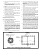
6. Remove the four flange screws (#22) securing the
hydraulic housing (#16) and cylinder mount plate
(#20) to the input shaft cover (#12) and remove the
hydraulic housing.
7. Remove the shift spool (#15) from the shift shaft (#10)
by sliding the shift spool out of the baseplate and
holding it secure while un-threading the shift spool.
NOTE: This connection is left hand thread.
8. If you purchased the rebuild kit (MBW Part Number
17368) go to step #12.
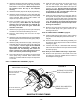
9. Remove the seal guide ring (#4) from the shift spool.
10. Remove the damaged or worn seals (#6) from the
shift spool (#15). Note the orientation of the
sealing lips of the seals to be replaced. Be careful
not to scratch the inner diameter sealing surface
of the shift spool when removing the seals.
11. Remove the four flanged capscrews (#21), the
cylinder cover (#19) and the cylinder gasket (#18).
Be sure to remove all of the gasket pieces from
the hydraulic housing to provide a good seal
surface for the new gasket.
12. Remove the bleeder screw (#14) from its port on the
hydraulic housing (#16). Thoroughly clean and
inspect the bleeder screw for damage. Replace if
needed.
13. Clean and inspect the shift spool (#15) and the
hydraulic housing (#16).
14. Reinstall the bleeder screw(#14) into its port in the
hydraulic housing (#16).
15. Install the new cylinder gasket (#18), the cylinder
cover (#19) and the four flanged capscrews (#21).
16. Remove all mount gasket material from the input
shaft cover (#12). Be careful to keep debris and
gasket pieces from entering the exciter assembly
when cleaning the cover.
17. If you purchased the rebuild kit (MBW Part Number
17368) go to step #20.
18. Assemble the new seals (#6) to the shift spool (#15).
Note the orientation of the seal lips. Hint: use
hydraulic oil to lubricate the seal inner diameter
before pressing onto the spool. Beware the slot
cut on the shift spool it may be sharp. Press the
seal on “WITH” the slot and NOT
“ACROSS” the
slot.
19. Assemble the new guide ring (#4) to the shift spool
(#15).
20. Thread the shift spool (#15) onto the shift shaft (#10).
Note the left hand thread.
21. Install a new mount gasket (#17) on the hydraulic
housing (#16).
22. Guide the hydraulic housing over the shift spool seals
and guide ring and secure the cylinder mount plate
(#20) to the input shaft cover (#12) using the four
flange screws (#22) removed in step 5 using
LOCTITE #243 on the screw threads. Note: Tighten
the screws in a criss-cross pattern, tighten evenly
to prevent cocking the cylinder mount plate.
23. Reinstall the 90 degree fitting (#13) into the hydraulic
housing (#16).
24. Clean and reattach the hydraulic line (#2) to the 90
degree fitting (#13) on the hydraulic housing. Be
sure the hydraulic line does not bind in the
grommet. Loosen and rotate the hydraulic fitting
(#13) and rotate it as required.
25. Follow the steps for Bleeding And Adjustment Of
Hydraulic Controls section of this manual.
26. Reinstall the side cover removed in step 2 using
LOCTITE #243 on the screw threads.
27. Lower engine deck to level position and tighten hex
head bolts (#32).
Bleeding And Adjustment of Hydraulic
Controls
Refer to MAIN ASSEMBLY, page 22. for side cover
removal.
1. Remove the six flange screws (#23) securing the side
cover (#16) to the recoil/oil drain side of the