
Network Hardware User Manual

- 12 -
baseplate. Loosen hex head bolts (#32) on the oil
drain side only. Lift the engine deck up to allow the
hydraulic guard to be removed.
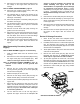
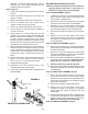
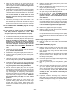
Refer to figure 2.
2. Position the handle in the locked position and set the
lock pin.
3. Check the hydraulic line (#4) for loose fittings and
tighten as needed.
4. Remove the pipe plug (#2) from the control head.
5. Loosen the bleeder screw (#1) located at the
hydraulic control housing of the exciter.
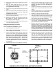
6. Fill the control head with hydraulic fluid as shown.
7. Place a drip pan or shop rag below the bleeder to
catch any excess oil.
8. Slowly operate the control handle (#3) from the
forward to the reverse position while watching the
bleeder screw hole for air bubbles. If no air bubbles
are seen, hold the control handle in the reverse
position and tighten the bleeder. If air bubbles are still
present at the end of the stroke, refill the control head
with hydraulic oil and repeat this procedure.
9. After the air bubbles have been removed, tighten the
bleeder screw (#1) and adjust the hydraulic oil level
in the control head by pushing the shift handle to the
forward position and then pulling it into the reverse
position until it stops. Repeat this procedure two
times.
10. With the shift lever in the forward position and the
handle in the locked position, oil level should be
about 1-1/4” to 1-1/2” from top of control head.
11. Reinstall the pipe plug (#2).
12. Reinstall the side cover removed in stop 1 using
LOCTITE #243 on the screw threads.
13. Lower engine deck to level position and tighten hex
head bolts (#32).
Baseplate Disassembly Procedure
Reference the Main Disassembly Procedure (diesel) or
(gasoline) Engine, listed earlier in this section, to
separate the engine deck from the baseplate.
Refer to MAIN ASSEMBLY, page 22.
1. If installed, remove the four socked head capscrews
(#39), extension plates (#12) and bushings (#13)
from the sides of baseplate (#7).
2. Remove the twelve hex head flange screws (#24)
securing the side covers (#16) to the baseplate.
3. Remove the four hex head flange screws (#25)
securing the bellows mounts (#18) to the baseplate
and remove the bellows mounts and bellows (#5).
4. Disconnect the hydraulic line (#2) from the hydraulic
fitting.
5. Remove the four hex head flange screws (#24)
securing the hydraulic guard (#17) to the baseplate
and remove the hydraulic guard and hydraulic line
from the baseplate.
Refer to BASEPLATE ASSEMBLY, page 24.
6. Remove the hex head flange screw (#22) and washer
(#14) securing the pulley (#19) to the input shaft (#16)
and remove the pulley.
7. Remove the twenty hex head flange screws (#22)
securing the baseplate cover (#13) to the baseplate
(#15) and remove the baseplate cover.
8. Remove the oil drain plug (#25) and completely drain
the exciter oil into a drain pan. Examine the oil for
metal chips as a precaution to future troubles.
9. Note the position of the gear timing marks.
10. Remove the socket head capscrews (#24) securing
the exciter weights (#17) to the shafts and remove the
exciter weights.
Refer to LOWER SHAFT ASSEMBLY, page 26.
11. Place a shop rag under the hydraulic housing (#16)
to catch the oil and remove the four flange screws
(#22) securing the cylinder mount plate (#20) to the
input shaft cover and remove the hydraulic housing
(#16) from the baseplate.
12. Remove the 90 degree hydraulic fitting (#13).
13. Remove the four hex head flange screws (#21)
securing the cylinder cover (#19) to the hydraulic
housing (#16) and remove the cylinder cover and
gasket (#18).
14. Remove the shift spool (#15) from the shift shaft (#10)
by sliding the shift spool out of the baseplate and
holding it secure while unthreading the shift spool.
NOTE: This connection is left hand thread.
Refer to BASEPLATE ASSEMBLY, page 24.
*35+<'5$8/,&6
),*85(
2,//(9(/