
Network Hardware User Manual
- 17 -
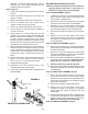
Control Head Assembly Procedure
Refer to HANDLE ASSEMBLY, page 28.
1. Clean and dry all parts to be assembled.
2. Press the slide bushing (#14) into the control housing
(#13).
3. Press the hydraulic seal (#2) onto the rack gear
(#15). Be careful to orient the seal lip to face the
shaft guide housing (#16). Tip: Use approved
hydraulic oil to lubricate the seal inside diameter
to ease assembly. See Maintenance Section for
type of hydraulic oil.
4. Assembly the hex head cap screw (#26) and washer
(#31) to the rack gear using LOCTITE #243 thread
locker sealant on the threads.
5. Install the O-ring (#7) onto the shaft guide
housing(#16).
6. Install the guide ring (#3) onto the rack gear (#15).
7. Lubricate the inside of the shaft guide housing (#16)
and the rack gear subassembly with hydraulic oil.
See Maintenance Section for type of hydraulic oil.
8. Slide the rack gear subassembly into the shaft guide
housing (#16) until the guide ring (#3) is fully inserted
into the shaft guide housing (#16).
9. Slide the shaft guide housing/rack gear subassembly
into the control housing (#13) while guiding the rack
gear (#15) into the slide bushing (#14).
10. Secure the shaft guide housing (#16) to the control
housing (#13) with the four hex head flange screws
(#29) using LOCTITE #243 thread locker sealant on
the threads and torque the cap screws to 13 ft.-lbs.
11. Push the rack gear (#15) toward the pipe plug end of
the control housing (#13) until it is approximately
0.90” from the end of the control housing. Note: this
measurement is approximate.
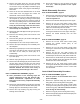
12. Install the O-rings (#4 and #5) on the pinion gear
(#24). Tip: Use hydraulic oil to lubricate the O-
rings to ease assembly.
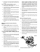
13. Slide the pinion gear (#24) with seals into the control
housing (#13). Note the positions of the rack gear
and the pinion gear and align as shown, use care
when meshing the gears.
14. Install the external snap ring (#6) onto the pinion gear
shaft (#24).
15. Install the hydraulic adapter (#23) into the shaft guide
housing (#16) using hydraulic oil as a seal lubricant.
16. Install the hydraulic fitting (#1) into the hydraulic
adapter (#23) using hydraulic oil as a seal lubricant.
17. Install the pipe plug (#8) and the sealing washer (#9)
into the control housing (#13) all the way, but do not
tighten.
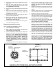
Handle Assembly Procedure
Refer to HANDLE ASSEMBLY, page 28.
1. Install the control head assembly into the handle tube
(#22) and secure the handlebars (#19 and #20) to the
handle and control head with the six hex head flange
screws (#32) using LOCTITE #243 thread locker
sealant on the threads.
2. Slide the two control handles (#18) onto the control
head and secure them with the two socket head cap
screws (#28) using LOCTITE #243 thread locker
sealant on the threads.
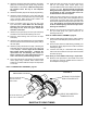
3. Thread one hex nut (#33) onto the threaded rod
(#10).
4. Install the threaded rod(#10) into the handle angle
mount (#25) and thread on the other jam nut (#33).
5. Thread the handle bumper shockmount (#12) onto
the threaded rod.
6. Connect the shock mounts (#11) to the handle from
inside the tube with four 8mm hex head flange screws
(#34) using LOCTITE #243 thread locker sealant on
the threads.
7. Secure the spindle mounts (#21) to the shockmounts
with four 8mm flat head socket screws (#35) using
LOCTITE #243 thread locker sealant on the threads.
Refer to MAIN ASSEMBLY, page 22.
8. Install the handle mounts (#6) onto the handle
assembly.
9. Route the hydraulic line (#2) through the handle tube.
10. Secure the handle assembly to the engine deck with
four hex head flange screws (#29).
11. Secure the hydraulic line (#2) to the hydraulic control
head fitting.
Final Assembly
Refer to engine pages (Gasoline or Diesel)
1. Lower engine assembly onto baseplate. Use care to
route hydraulic hose through engine deck and up
handle tube.
2. Install four bolts, lock washers and washers (#11, #14
& #15) or (#28, #29 & #30) through the engine block
into engine deck.
3. Install four bolts (#34) lockwashers (#36) and
washers (#37) through engine deck into
shockmounts on bottom plate.
4. Refer to the Belt Adjustment section of this manual
to complete assembly.
5. Bleed the hydraulics according to the Bleeding and
Adjustment of Hydraulic Controls section of this
Manual.