
Network Hardware User Manual

- 10 -
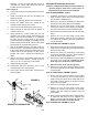
11. Remove the four hex head capscrews (#29) securing
the rollcage to the engine deck and remove the
rollcage.
Refer to DIESEL ENGINE ASSEMBLY, page 32.
12. Disconnect the negative “black” battery cable (#9)
from the engine mount bolt (#28).
13. Use electrical tape to enclose the terminal of the
negative “black” battery cable to prevent “accidental
discharge” of the battery.
14. Disconnect the positive “red” battery cable (#10) from
the starter of the engine.
15. Use the electrical tape to enclose the terminal of the
positive “red” battery cable to prevent “accidental
discharge” of the battery.
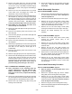
16. Remove the three 6mm bolts (#34) securing the
ignition box to the mount (#13).
17. Remove the four hex head screws (#33) securing the
battery box (#18) to shockmounts, remove battery
box and cables. Then remove four hex head flange
screws (#27) and mounting brackets (#20).
18. Remove the four hex head capscrews (#28) securing
the engine to the engine deck and remove the
engine.
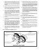
Main Disassembly Procedure (Gasoline
Engine)
Refer to MAIN ASSEMBLY, page 22. for disassembly.
1. Clean all visible debris from the machine before
servicing.
2. Remove the four hex head capscrews (#32) securing
the engine deck (#4) to the baseplate (#7). Use
caution as the engine deck will drop down.
Refer to GASOLINE ENGINE ASSEMBLY, page 30.
Sections of this manual for belt guard & belt
removal.
3. Remove the four socket head capscrews (#12)
securing the belt guard (#7) to the mount plate (#9)
and remove the beltguard.
4. Slide the belt (#3) off the clutch (#4).
5. Remove the two flange screws (#23) securing the
bellows retainer (#20), and remove the retainer.
6. Push the lip of the bellows (#5) through the hole in the
engine deck.
7. Disconnect the hydraulic line (#2) from the control
head in the handle assembly. Keep the end of the
hydraulic line and control head fitting free of dirt and
debris by using tape. Be careful to use a drain pan
to catch the hydraulic oil.
8. Use the main lift hook on the roll cage (#8) to
separate the engine deck from the baseplate. Be
careful to guide the hydraulic line through the
handle assembly and engine deck as the
subassemblies are separated to prevent damage
to components and personal injury. If further
disassembly of the engine deck is required proceed
to step 9. If baseplate service is required refer to
Baseplate Disassembly Procedure section of this
manual.
9. Disconnect the throttle cable (#19) from the engine.
10. Remove the handle assembly by removing the four
flange screws (#27) securing the handle mount (#6)
to the engine deck.
11. Remove the four hex head capscrews (#29) securing
the rollcage to the engine deck and remove the
rollcage.
12. Remove the four hex head capscrews (#11) securing
the engine to the engine deck and remove the
engine.
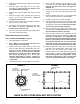
Exciter Oil Change Procedure
1. Clean all dirt and debris from baseplate before
disassembly to prevent contamination of exciter oil.
2. If installed, remove the two 1” socket head capscrews
(#1) and bushings (#3) securing the baseplate
extensions (#2) to the baseplate (#4) from the recoil/
oil drain side of the baseplate.
3. Tilt the plate toward a drain pan to aid in the removal
of all used oil and particles.
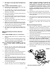
4. Remove the socket head pipe plug (#5) from the
baseplate and drain the oil. Examine the oil for
metal chips as a precaution to future troubles.
5. Tip the plate opposite the drain hole, and fill the
baseplate through the pipe plug opening with exciter
oil to level specified in the Fluid Levels section of this
manual. Use only MBW Ground Pounder Exciter Oil.
6. Reinstall the socket head pipe plug using sealant
(LOCTITE #565).
*35(;&,7(52,/'5$,1
),*85(