
User`s guide
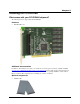


PCI-DIO48H User's Guide Installing the PCI-DIO48H
12
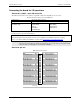
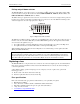
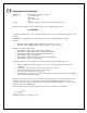
Cabling
The red stripe
identifies pin # 1
50-pin Female
IDC connector
50-pin Female
IDC Connector
1
2
49
50
2
50
1
49
Figure 2. C50FF-x cable
Field wiring and signal termination accessories
You can use the following screw terminal boards to terminate field signals and route them into the PCI-DIO48H
using the C50FF-x cable.
CIO-MINI50 – 50-pin screw terminal board.
CIO-SPADE50 — 16" X 4" termination panel which mates with both 37-pin and 50-pin connectors.
SCB-50 – 50 conductor, shielded signal connection/screw terminal box provides two independent 50-pin
connections.
Details on these products are available on our web site at www.mccdaq.com/products/screw_terminal_bnc.aspx.
CIO-ERB24 – 24 Form C relays, 6 Amp relay accessory board for digital signal conditioning.
CIO-SERB24/FD – 24 Form C relays, 10 Amp, fault detecting relay accessory board with socketed and
field-replaceable relays.
CIO-ERB48 – 48 Form C relays, 6 Amp, relay, 50-pin accessory board for digital signal conditioning.
CIO-SERB48 – 48 Form C relays, 10 Amp relay accessory board with socketed relays.
SSR-RACK24 – 24-channel, solid-state relay mounting rack for digital signal conditioning.
SSR-RACK48 – 48-channel, solid-state relay mounting rack with quad-format modules.
Details on these products are available on our web site at www.mccdaq.com/products/signal_conditioning.aspx.
For additional information about digital interfacing…
Detailed information regarding digital interfacing is contained in MCC's Guide to Signal Connections. This
document is available on our web site at www.measurementcomputing.com/signals/signals.pdf.