
User`s guide


7
Chapter 1
Introducing the PCI-DIO48H
Overview: PCI-DIO48H features
This manual explains how to install and use the PCI-DIO48H board. The PCI-DIO48H is a logic-level digital
I/O board designed for the PCI-bus.
The PCI-DIO48H provides 48-bits of digital I/O. The I/O is organized into two 24-bit groups based on an
82C55 mode 0 emulation. Each 24-bit group is divided into three eight-bit ports — PORT A, B, and C. PORT C
can be split into two four-bit nibbles — C-HI and C-LO. Each of these ports may be individually programmed
as input or output.
All digital inputs are LSTTL. The output signals are buffered high output drive TTL. The digital output drivers
are 74ABT244 chips that can sink 64 mA and source 15 mA. The input buffers are 74LS373 chips and have the
standard high input impedance of the 74LS series devices.
Digital I/O lines are accessible through a 50-pin header connector. The board has a slow blow fuse rated at
1 amp that protects the +5 V User Output on the connector. One spare fuse is provided.
On power up and reset, all I/O bits are set to input mode. If you are using the board to control items that must be
OFF on reset, install pull-down resistors. Each board is equipped with open locations where you can install SIP
resistor networks for either pull-up or pull-down.
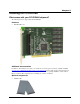
The PCI-DIO48H board is completely plug-and-play, with no jumpers or switches to set. All board addresses
are set by the board's plug-and-play software. Board configuration is controlled by your system's BIOS.
Software features
For information on the features of InstaCal and the other software included with your PCI-DIO48H, refer to the
Quick Start Guide that shipped with your device. The Quick Start Guide is also available in PDF at
www.mccdaq.com/PDFmanuals/DAQ-Software-Quick-Start.pdf.
Check www.mccdaq.com/download.htm for the latest software version or versions of the software supported
under less commonly used operating systems.