
Installation Guide


Finding breaks in the loop wire
Breaks in the loop wire are usually the result of
unconscious physical damage to the wire such as when
gardening with a shovel. In countries with ground frost,
even sharp stones that move in the ground can damage
the wire. Breaks can also be due to the high tension in the
wire during installation.
Mowing the grass too low right after the installation can
damage wire insulation. Certain damage to the insulation
may not cause disruptions until several weeks or months
later. To avoid this, always select the maximum cutting
height the first weeks after installation and then lower the
height one step at a time every second week until the
desired cutting height has been reached.
A defective splicing of the loop wire can also lead to
disruptions first several weeks after the splice was done. A
faulty splice can, for example, be the result of the original
coupler not being pressed together hard enough with a
pair of pliers, or a coupler of lower quality than original
coupler has been used. Please first check all known
splices before further troubleshooting is done.
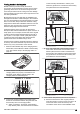
A break can be located by gradually halving the distance
of the loop wire where the break may have occurred until
there is only a very short section of the wire left.
1. Make sure the indicator lamp in the charging station
flashes blue, which indicates a break in the boundary
loop. See
Indicator lamp in the charging station on
page 40
2. Check that the boundary wire connections to the
charging station are properly connected and not
damaged. Check that the indicator lamp in the
charging station is still flashing blue.
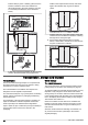
POWER R L GUIDE
3. Connect the charging station to the power supply.
Switch the connections between the guide wire and
the boundary wire in the charging station.
a) Switch connection L and Guide. If the indicator
lamp flashes yellow, then the break is somewhere
on the boundary wire between L and the point
where the guide wire is connected to the boundary
wire (thick black line in the illustration).
Guide
b) Put L and Guide back in their original positions.
Then switch R and Guide. If the indicator lamp
flashes yellow, then the break is somewhere on
the boundary wire between R and the point where
the guide wire is connected to the boundary wire
(thick black line in the illustration).
Guide
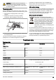
4. If the indicator lamp flashed yellow in test 3a) above.
a) Reset all connections to their original positions.
Then disconnect R. Connect a new loop wire to R.
Connect the other end of this new loop wire
somewhere at the centre of the installation.If the
175 - 001 - 17.03.2017 43