Operator's manual ROB R600, ROB R800, ROB R1000 Read the operator's manual carefully and make sure that you understand the instructions before you use the product.
Contents 1 Introduction 1.1 Memo..................................................................... 3 1.2 Product description................................................ 3 1.3 Product overview....................................................5 1.4 Symbols on the product......................................... 6 2 Safety 2.1 Safety definitions....................................................7 2.2 General safety instructions.....................................7 2.
1 Introduction 1.1 Memo Serial number: PIN code: Product registration key: The Product registration key is a valuable document and must be stored in a safe place. This key is necessary for example to register the produkt on McCULLOCH's website or unlock the robotic lawnmower in the event of a lost PIN code. The product registration key is provided in a separate document in the product packaging. If the robotic lawnmower is stolen, it is important to notify McCULLOCH of this.
1.2.4 Movement pattern The movement pattern of the robotic lawnmower is random, which means that a movement pattern is never repeated. With this cutting system the lawn is mown evenly without any mowing lines from the robotic lawnmower. The blades must be in good condition to obtain the best mowing result. In order to keep the blades sharp for as long as possible it is important to keep the lawn free from branches, small stones and other objects. Replace the blades regularly for the best mowing result.
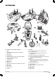
1.3 Product overview 3 2 4 5 7 1 8 6 9 10 28 16 11 13 17 15 12 18 21 19 14 24 22 20 26 23 27 25 The numbers in the illustration represent: 1. Body 2. Cover to display, keypad and cutting height adjustment 3. Stop button 4. Contact strips 5. LED for operation check of the charging station, boundary wire and guide wire 6. Charging station 7. Carry handle 8. Battery cover 9. Blade disc 10. Chassis box with electronics, battery and motors 11. Main switch 12. Rear wheel 13. Charging strip 14.
1.4 Symbols on the product These symbols can be found on the robotic lawnmower. Study them carefully. WARNING: Read the user instructions before operating the robotic lawnmower. The low voltage cable must not be shortened, extended or spliced. Do not use a trimmer nearby the low voltage cable. Be careful when trimming edges where the cables are placed. Operate the disabling device before you use or lift the product. WARNING: Operate the disabling device before working on or lifting the machine.
2 Safety 2.1 Safety definitions 2.2 General safety instructions Warnings, cautions and notes are used to point out specially important parts of the operator's manual. The following system is used in the Operator’s Manual to make it easier to use: WARNING: Used if there is a risk of injury or death for the operator or bystanders if the instructions in the manual are not obeyed.
Warning! Automatic lawnmower! Keep away from the machine! Supervise children! • • Warning! Automatic lawnmower! Keep away from the machine! Supervise children! • • • • • • Use the HOME function or switch off the main switch when persons, especially children or pets, are in the cutting area. It is recommended to program the lawnmower for use during hours when the area is free from activity, e.g. at night. See Timer on page 22.
2.3.4 In the event of a thunderstorm 3. Carry the robotic lawnmower by the handle under the robotic lawnmower with the blade disc away from the body. To reduce the risk of damage to electrical components in the robotic lawnmower and its charging station, we recommend that all connections to the charging station are disconnected (power supply, boundary wire and guide wires) if there is a risk of a thunderstorm. CAUTION: Do not lift the robotic lawnmower when it is parked in the charging station.
3 Installation 3.1 Presentation This chapter contains information that is important to be aware of when planning the installation. Before starting the installation make yourself familiar with what is included in the carton.
3. Read carefully through all the steps before the installation. 4. Check that all parts for the installation are included. See Presentation on page 10. • • • • • • • • • • • Robotic lawnmower Charging station Loop wire for boundary loop and guide wire Power supply Low voltage cable Pegs Connectors for the loop wire Screws for the charging station Measurement gauge Couplers for the loop wire Cable markers • • • • Protection from water spray for instance from irrigation. Protection from direct sunlight.
WARNING: Applicable to USA/Canada. If power supply is installed outdoors: Risk of Electric Shock. Install only to a covered Class A GFCI receptacle (RCD) that has an enclosure that is weatherproof with the attachment plug cap inserted or removed. If the installation is done in a working area with a steep slope, the charging station should be placed at the bottom of the slope. This makes it easier for the robotic lawnmower to follow the guide wire to the charging station.
permitted to place the power supply on the ground. min 30 cm / 12” CAUTION: It is not permitted to make new holes in the base plate. Only the existing holes may be used to secure it to the ground. WARNING: No parts of the power supply must under any circumstances be changed or tampered with. The low voltage cable must not be shortened or extended. CAUTION: Do not tread or walk on the charging station’s base plate.
• have grown over the wire making it no longer visible. Use a hammer/plastic mallet and pegs. Bury the wire. Bury the boundary wire if you want to dethatch or aerate the lawn. If necessary, both methods can be combined so one part of the boundary wire is stapled down and the other is buried. The wire can be buried for instance using an edge cutter or a straight spade. Make sure to lay the boundary wire at least 1 cm / 0.4 in. and a maximum of 20 cm / 8 in. in the ground. 3.5.
When the working area is divided by a paving stone path that is level with the lawn, it is possible to allow the robotic lawnmower to run over the path. It can be an advantage to lay the boundary wire under the paving stones. The boundary wire can also be laid in the joint between the paving stones. Ensure that the tiles are in level with the lawn to avoid excessive wear on the robotic lawnmower.
15- % Secondary area >15 cm / >6" 100 cm / 40" However, the boundary wire can be laid across a slope steeper than 15% if there is an obstacle that the robotic lawnmower is allowed to collide with, for example, a fence or a dense hedge. Main area The MAN operating mode must be used as the robotic lawnmower cannot travel on its own from the secondary area to the charging station. See Operation selection on page 33.
• Use a hammer to knock the pegs into the ground. Exercise care when knocking the pegs and make sure the wire is not under strain. Avoid sharp bends. If the boundary wire is to be buried: • 15- cm / 6-" 100 cm / 40" Make sure to lay the boundary wire at a minimum of 1 cm / 0.4 in. and a maximum of 20 cm / 8 in. in the ground. The wire can be buried for instance using an edge cutter or a straight spade. Note: Extra wire must not be placed in coils outside the boundary wire.
the coupler fully. Use a polygrip to completely press down the button on the coupler. 4. Press the connector onto the metal pin, Press the connector onto the contact pin, marked L (left) and R (right), on the charging station.Carefully check that the connector is properly fitted. 3.7 Installation of the guide wire 3.6 Connecting the boundary wire CAUTION: The boundary wire must not be crossed when connecting it to the charging station.
• The robotic lawnmower follows the guide wire on the same side of the wire to and from the charging station. This means that the guide wire is to the right of the robotic lawnmower when the mower travels to the charging station while it is to the left of the mower when the mower travels away from the charging station. • If the guide wire has to be installed on a steep slope, it is an advantage to lay the wire at an angle to the slope.
used to connect each boundary wire. Insert the guide wire in the centre hole in the coupler. Check that the wires are fully inserted into the coupler so that the ends are visible through the transparent area on the other side of the coupler. See Indicator lamp in the charging station on page 42 if the lamp does not indicate a solid or flashing green light. 3.9 First start-up and calibration • Use a polygrip to completely press down the button on the coupler.
wire. Place the robotic lawnmower about 2 m from the guide wire, facing the guide wire. 3. Select HOME mode by pressing the house symbol key and pressing OK when the cursor is at Home. Press START and close the hatch. 4. Check that the robotic lawnmower follows the guide wire all the way to the charging station and that it docks with the charging station.
The following section summarises the menu selections found in the main menu and provides more detailed information about how each function is used and which setting options are available. 3.12.1 Main menu Timer The timer function is an ideal tool to control which periods the robotic lawnmower should not mow, for example when children are playing in the garden. Installation (only for ROB R800, ROB R1000) This menu function is used to customize the installation.
3.13.1 Timer suggestions ROB R600 Work area Work days per week Work hours per day Suggested time interval 100 m2 / 1100 sq. ft 5 3 07:00 am - 10:00 am 7 2.5 07:00 am - 9:30 am 5 6.5 07:00 am - 01:30 pm 7 4.5 07:00 am - 11:30 am 5 13 07:00 am - 08:00 pm 7 9 07:00 am - 04:00 pm 6 16 07:00 am - 11:00 pm 7 13.5 07:00 am - 08:30 pm Work days per week Work hours per day Suggested time time interval 5 3 07:00 am - 10:00 am 7 2 07:00 am - 09:00 am 5 5.
3.14 Installation - ROB R800, ROB R1000 • The following five options can be selected; - Never (0%) INSTALLATION Remote start 1 Remote start 2 Test settings Drive past wire The following operating settings are available via this selection in the main menu. • • • • Remote start 1: To control the robotic lawnmower so that it can easier reach remote parts of the garden. Remote start 2: To control the robotic lawnmower so that it can easier reach remote parts of the garden.
Park the robotic lawnmower in the charging station and select Test OUT - Remote start 1. The robotic lawnmower will then leave the charging station straight away along the guide wire and begin mowing after the designated distance. SECURITY Change PIN code Security level How to measure the distance from the charging station to a remote area: Enter a distance which beyond any doubt exceeds the real figure. The maximum distance that can be entered is 100 m / 328 ft.
3.15.2.3 Alarm This function means that an alarm sounds if the PIN code is not entered within 10 seconds after the STOP button has been pressed or the robotic lawnmower has been lifted up for any reason. A ticking noise indicates that the PIN code must be entered to prevent triggering the alarm. The alarm can be turned off at any time by entering the correct PIN code. 3.15.3 New loop signal The loop signal is randomly selected to create a unique link between the robotic lawnmower and the charging station.
3.16.6 Calibrate guide, ROB R600 The Calibrate guide function allows you to test if the robotic lawnmower can follow the guide wire out from the charging station. Remote start Proportion Proportion To test the guide wire: 1. Place the robotic lawnmower in the charging station. 2. Select Calibrate guide and press OK.
3.
3.
3.19 Yard layout examples The robotic mower’s behaviour is controlled to a certain extent by what settings are made. Adapting the robotic lawnmower's settings according to the shape of the lawn makes it easier for the robotic lawnmower to frequently reach all parts and therefore achieve a perfect mowing result. Different layouts require different settings. The following pages outline a number of layout examples with installation proposals and settings.
3.19.3 A number of islands and a 25% slope Area 600 m2 / 4300 sq. ft. Timer 7 am - 11 pm (factory setting) Monday-Sunday Remote start - 270˚ Rarely (factory setting) Proportion Remarks Place the charging station in the lower part of the working area. Lay the guide wire at an angle over the steep slope. Make sure guide wire is laid according to recommendations in 90˚ Laying and connecting the guide wire on page 19 3.19.
3.19.6 Unsymmetrical working area with a narrow passage and a number of islands Area 150 m2 / 1600 sq. ft. Timer 7 am - 5 pm Monday, Wednesday, Friday Remote start - 2 m / 7 ft Rarely (factory setting) Proportion Remarks The guide wire must be placed along the narrow passage to ensure that the robotic lawnmower can with ease locate the charging station from the right hand side of the working area. Select Proportion: Rarely as the right hand area is a small fraction of the total area.
4 Operation 4.1 Main switch WARNING: Read the safety instructions carefully before you start your robotic lawnmower. 4.3 Operation selection The operation selection button is symbolised by a house. When the button has been pressed, the selected operation mode is shown in the display. By consecutively pressing the button many times, one can choose between three different operation modes. WARNING: Keep your hands and feet away from the rotating blades.
4.4 Stop 1. Press the STOP button. The robotic lawnmower stops, the blade motor stops and the hatch opens. If the working area is for example 360 m2 / 3875 in. size, ROB R1000 must operate for 7,5 hours a day. The times are approximate and depend for instance on grass quality, blade sharpness and battery age. WARNING: Use the timer to avoid mowing when there are usually children, pets and anything else that could be damaged by the rotating blades on the lawn.
Timer setting Period 2 (C): 20:00 - 23:00 ROB R600 Active period (A): 06:00 - 17:00 Operation, A + C = max. hours 13 Active period (C): 20:00 - 22:00 Charging/Standby, B + D = min. hours 11 The robotic lawnmower will operate between 06:00 and 17:00. It will begin again at 20:00 but stops running at 23:00 due to standby mode until it starts again at 06:00. 24 h D at r pe O a St n io Mo Ch wing arg i ng A by nd 4.
5 Maintenance 5.1 Introduction - maintenance For better operating reliability and longer service life: check and clean the robotic lawnmower regularly and replace worn parts if necessary. All maintenance and servicing must be done according to McCULLOCH's instructions. See Guarantee terms on page 50. When the robotic lawnmower is first used, the blade disc and blades should be inspected once a week. If the amount of wear during this period has been low, the inspection interval can be increased.
If the operating times for the robotic lawnmower are shorter than normal between charges, this indicates that the battery is getting old and eventually needs replacing. The battery is fine as long as the robotic lawnmower maintains a well-cut lawn. 5.4.1 Replacing the battery 5.3.1 To replace the blades 1. Set the main switch to position 0. 2. Turn the robotic lawnmower upside down. Place the robotic lawnmower on a soft and clean surface to avoid scratching the body and the hatch. 3. Remove the 3 screws.
lawnmower in good condition and create the best conditions for a new season without any disruptions. Service usually includes the following: • • • • • Thorough cleaning of the body, the chassis, the blade disc and all other moving parts. Testing of the mower’s function and components. Checking and if required replacement of wear items such as blades and bearings. Testing the mower’s battery capacity as well as a recommendation to replace battery if necessary.
6 Troubleshooting 6.1 Introduction - troubleshooting In this chapter, a number of messages are listed which may be shown in the display if there is a malfunction. There is a proposal as to the cause and steps to take for each message. This chapter also presents some symptoms that can guide you if the robotic lawnmower does not work as expected. More suggestions for steps to take in the event of malfunction or symptoms can be found on www.mcculloch.com. 6.
Message Cause Outside working area The boundary wire connections to the charging station are crossed. Action Check that the boundary wire is connected correctly. The boundary wire is too close to the edge of Check that the boundary wire has been laid the working area. according to the instructions in Boundaries within the working area on page 15. The working area slopes too much. The boundary wire is laid in the wrong direction around an island.
Message Cause Action Stuck in charging sta- There is an object in the way of the robotic tion lawnmower preventing it from leaving the charging station. Remove the object. Upside down Turn the robotic lawnmower the right way up. The robotic lawnmower is leaning too much or has turned over. Needs manual charg- The robotic lawnmower is set in the MAN op- Place the robotic lawnmower in the charging ing erating mode. station. This behaviour is normal and no action is required.
6.3 Indicator lamp in the charging station For a fully functional installation, the indicator lamp in the charging station must emit a solid green light. If something else appears, follow the troubleshooting guide below. If you still need help with troubleshooting, please contact your local McCULLOCH representative. Light Cause Action Solid green light Everything in order No action required Green flashing light The signals are good and ECO mode is activated. No action required.
6.4 Symptoms If your robotic lawnmower does not work as expected, follow the troubleshooting guide below. There is a FAQ (Frequently Asked Questions) on www.mcculloch.com which provides more detailed answers to a number of standard questions. Contact your local McCULLOCH representative if you still cannot find the reason for the fault. Symptoms Cause The robotic lawnmow- The boundary wire is not laid in a long er has difficulty dock- straight line that is far enough out from the ing. charging station.
Symptoms Cause Action The robotic lawnmow- Grass or other foreign object blocks the blade Remove and clean the blade disc. See Clean er mows for shorter disc. the robotic lawnmower on page 36. periods than usual between charges. Both the mowing and charging times are shorter than usual. The battery is spent. Replace the battery. See Battery on page 37. The robotic lawnmow- The robotic lawnmower has an inbuilt standby No action. er is parked for hours period according to the Standby time table.
Guide To rectify the fault you will need boundary wire, connector(s) and coupler(s): a) If the suspected boundary wire is short then it is easiest to exchange all of the boundary wire between L and the point where the guide wire is connected to the boundary wire (thick black line). b) If the suspected boundary wire is long (thick black line) then do as follows: Put L and Guide back to their original positions. Then disconnect R. Connect a new loop wire to R.
and connect a new boundary wire to L. Connect the other end of this new wire at the middle of the suspected wire section. Follow the same approach as in 3 a) and 3b) above. 5. When the break is found, the damaged section must be replaced with a new wire. Always use original couplers.
7 Transportation, storage and disposal 7.1 Transportation The contained lithium-ion-batteries are subject to the Dangerous Goods Legislation requirements. For commercial transports e.g. by third parties or forwarding agents, special requirement on packaging and labeling must be observed. Consult an expert for hazardous material for preparation of the item being shipped. Please also observe possibly more detailed national regulations.
8 Technical data 8.1 Technical data Dimensions ROB R600 ROB R800 ROB R1000 Length, cm /in. 60 / 24 60 / 24 60 / 24 Width, cm / in. 44 / 17 44 / 17 44 / 17 Height, cm / in. 26 / 10 26 / 10 26 / 10 Weight, kg / lbs 7 / 15.4 7 / 15.4 7 / 15.4 Electrical system ROB R600 ROB R800 ROB R1000 Battery, Lithium-Ion, 18 V/2.1 Ah Art.
Mowing ROB R600 ROB R800 ROB R1000 Maximum length boundary wire, m / ft. 400 / 1300 400 / 1300 400 / 1300 Maximum length guide wire, m / ft. 100 / 350 100 / 350 100 / 350 600 /0.15 800 / 0.2 1000 / 0.
9 Warranty 9.1 Guarantee terms McCULLOCH guarantees this product’s functionality for a period of two years (from date of purchase). The guarantee covers serious faults relating to materials or manufacturing faults. Within the guarantee period, we will replace the product or repair it at no charge if the following terms are met: • • The robotic lawnmower and the charging station may only be used in compliance with the instructions in this Operator’s Manual.
358 - 002 - Warranty - 51
Copyright © 2017 Husqvarna AB. All rights reserved. McCulloch and other product and feature names are trademarks of the Husqvarna Group. All measurements quoted are approximate. www.mcculloch.