Operator′s manual M48 M53 S Please read the operator’s manual carefully and make sure you understand the instructions before using the machine.
KEY TO SYMBOLS Key to symbols Other symbols/decals on the machine refer to special certification requirements for certain markets. WARNING! The machine can be a dangerous tool if used incorrectly or carelessly, which can cause serious or fatal injury to the operator or others. Always wear protective gloves. Please read the operator’s manual carefully and make sure you understand the instructions before using the machine. Always wear: • Regular cleaning is required. Visual check.
CONTENTS Contents KEY TO SYMBOLS Key to symbols ............................................................. Steps before using a new lawn mower ........................ CONTENTS Contents ...................................................................... SAFETY INSTRUCTIONS Personal protection ...................................................... Machine′s safety equipment ........................................ Checking, maintaining and servicing the machine′s safety equipment ......................
SAFETY INSTRUCTIONS Personal protection ! Engine brake handle • Vibration damping system • Muffler • Cutting equipment WARNING! You must use personal protection whenever you use the machine. • Hearing protection • Gloves must be worn when required, for example when fitting, inspecting or cleaning cutting attachments. • • Always wear heavy, long pants. Do not wear shorts, sandals or go barefoot. Cutting cover and protective cover • Wear sturdy, non-slip boots or shoes.
SAFETY INSTRUCTIONS Vibration damping system Your machine is equipped with a vibration damping system that is designed to minimize vibration and make operation easier. Checking, maintaining and servicing the machine′s safety equipment The handlebar system's steel tube and the cutting cover are designed to minimise the vibrations from the engine. The machine′s vibration damping system reduces the transfer of vibration between the engine unit/cutting equipment and the machine′s handle unit.
SAFETY INSTRUCTIONS Vibration damping system ! The handlebar system's steel tube and the cutting cover are designed to minimise the vibrations from the engine. Make sure the cutting cover is not damaged and that there are no visible defects such as cracks. WARNING! Never use a machine with faulty safety equipment. The machine’s safety equipment must be checked and maintained as described in this section. If your machine fails any of these checks contact your service agent to get it repaired.
SAFETY INSTRUCTIONS Before use: Fuel safety (Refuelling/Storage.) ! 1 Check that the engine brake works correctly and is undamaged. See the instructions under the heading Checking the braking effect. 2 Check that all handles and controls are undamaged and free of oil. 3 Check that the anti vibration system works and is not damaged. 4 Check that the muffler is securely attached and not damaged.
SAFETY INSTRUCTIONS General working instructions WARNING! This section describes basic safety precautions for working with the lawn mower. This information is never a substitute for professional skills and experience. If you get into a situation where you feel unsure about how to progress, stop and seek expert advice. Contact your dealer, service agent or an experienced lawn mower user.
SAFETY INSTRUCTIONS Cutting height • To raise the cutting height move the lever to the left and then backward. Shut down the engine before changing the cutting height. The cutting height adjustment is spring assisted. The cutting height can be adjusted in five different steps. Do not set the cutting height too low as there is a risk that the cutters might hit slopes with unevenness. Do not set the cutting height too low as there is a risk that the cutters might hit slopes with unevenness.
WHAT IS WHAT? What is what on the lawn mower? M48 1 Handle / handlebar 2 Engine brake handle 3 Starter handle 4 Cutting height control 5 Fuel tank 6 Air purge 7 Air filter 8 Lower handlebar 9 Oil tank 10 Cutting cover 11 Muffler 12 Spark plug 13 Cutter/cutting equipment 14 Cup spring 15 Cutter bolt 16 Cutter bracket 17 Engine shaft 18 Operator′s manual 10 – English
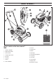
WHAT IS WHAT? 17 13 18 1 12 19 2 11 4 3 7 6 14 20 15 21 16 5 22 10 8 9 What is what on the lawn mower? M53 S 1 Handle / handlebar 2 Engine brake handle 3 Starter handle 4 Clutch lever 5 Cutting height control 6 Fuel tank 7 Oil tank 8 Air filter 9 Gear housing 10 Drive belt 11 Spark plug 12 Air purge 13 Lower handlebar 14 Cutting cover 15 Muffler 16 Protective cover 17 Cutter/cutting equipment 18 Cup spring 19 Cutter bolt 20 Cutter bracket 21 Engine shaft 22 Operator′s m
ASSEMBLY Fitting the handlebar Assembly Lift up the handlebar until the handlebar's upper tubular construction comes directly opposite to the handlebar's lower section. Tighten the knob correctly. • Position the cutter so that the cutting edge faces in the direction of rotation. • Fit the cup spring, make sure it centres correctly on the engine shaft. • Fit the washer and tighten the bolt correctly. The bolt should be tightened with a torque of 45-60 Nm.
FUEL HANDLING Fuel If the oil level is low, fill using engine oil up to the upper level on the dipstick. L FIL ER OV DO ! N TIO CAU WARNING! Always ensure there is adequate ventilation when handling fuel. FU LL Only use recommended engine oil. See the Technical data section. Petrol • Use good quality unleaded petrol. Leaded petrol can be used if unleaded petrol is not available. • Fuel should be at least 77 octane.
STARTING AND STOPPING Starting and stopping ! Pull the engine brake handle against the upper handlebar with your left hand. WARNING! Note the following before starting: Do not start a lawn mower unless the cutter and all covers are fitted correctly. Otherwise the cutter could come loose and cause personal injuries. Grip the starter handle, slowly pull out the cord with your right hand until you feel some resistance (the starter pawls grip), now quickly and powerfully pull the cord.
MAINTENANCE Maintenance Wash the filter with a liquid cleaning agent and water. After cleaning the filter should be oiled using engine oil. Proceed as follows: ! • Put the filter in a plastic bag and pour in new and clean engine oil. • Knead the plastic bag to distribute the oil equally in the filter. WARNING! Make sure the cutting attachment has stopped before cleaning, carrying out repairs or an inspection. Disconnect the HT lead from the spark plug.
MAINTENANCE Clean the filter by knocking the filter against a flat surface. Never use solvent with petroleum, for example, kerosene, or compressed air to clean the filter. Cutter When reassembling, make sure that the filter completely seals against the filter holder. Spark plug ! WARNING! The muffler gets very hot in use and remains so for a short time afterwards.
MAINTENANCE • Drain the oil by tipping the engine so that the oil runs out through the filler pipe. M48 M53 S Drive and gearbox M53 S Ensure the wheels and wheel axles are clean and free from leaves, grass, etc. It is also important to keep clean around the drive gearbox. • Remove the protective cover by unscrewing the screws. • Now guide the protective cover out under the stay and over the drive axle. • Clean the gearbox with a brush.
MAINTENANCE Below you will find some general maintenance instructions. Monthly maintenance 1 2 3 4 5 6 Daily maintenance L FIL ER OV T NO DO ION UT CA LL FU 1 Check that drive belt is not damaged and is not visibly defective. 1 Check that the engine brake handle works safely. 2 Brush leaves, grass and the like off of the lawn mower. 2 Clean the gearbox. 3 Check the oil level. 3 Check the fuel filter and the fuel hose. Replace if necessary. 4 Clean the air intake on the starter.
TECHNICAL DATA Technical data M48 M53 S 158 190 Engine Cylinder displacement, cm3 Cylinder bore, mm 65,1 68,3 Stroke, mm 47,5 51,8 Ignition system Spark plug Champion, BS 19 LM Champion, BS 19 LM Electrode gap, mm 0,76 0,76 Fuel tank capacity, litre 1 1 Oil tank capacity, litre 0,6 0,6 Engine oil SAE 30 SAE 30 25,3 33,0 Sound power level, measured dB(A) 95 97 Sound power level, guaranteed LWA dB(A) 96 98 5,6 5,3 5,8 4,4 Cutting system BioClip BioClip The cutting height
1140250-26 ´®z+H9"¶6P¨ ´®z+H9"¶6P¨ 2005-06-27