AWICCULLOCH CHIPPER/SHREDDER o UK a OWNER’S MANUAL READ CAREFULLY 287
., m 1 WARNING: TO REDUCE THE POTENllAL FOR ANY INJURY, COMPLY WITH THE FOLLOWfNG SAFETY INSTRUCTIONS. FAILURE TO COMPLY WfTH THE lNSTRUCTfONS MAY RESULT IN PERSONAL INJURY. .. .. . . . .. . . .. . .. ● n tfre cumng mecnamsm stnf(es any fore~n otqact or n TRAINING your machine should stari making an unusual noise or Read this owner’s manual carefully in its entirety before vibration, immediately stop the engine, disconnect the attempting to assemble or operate this machine.
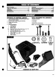
D SAFETVRULES ..............................................................2 TABLE OF CONTENTS .................................................3 ASSEMBLY ..................................................................4-5 OPERATION ................................................................8-8 MAINTENANCE .............................................................9 STORAGE .....................................................................10 ..................................
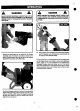
— DANGER A ● Assemble six(6) l/4-20x .50screws, pm,vided in parts bag, through afignsd holes. Do not tighten. “” ““ ● Position Hopper in position level with the unit and tighten all six (6) screws seourely. There are rotating cutting blades inside the Chipper/ Shredder housing that will cause serious injury. DO NOToperatemachlns unless ChlpperChuteand Shredder Hopper are seourely installed.
c) STEP 4: INSTALL DISCHARGE DEFLECTOR ● “Position discharge deflector (item C) as shown iassY. . Attach deflector to shredder housing using the four (4) l/420 x .50 one-way screws (item D), eight (8) fiatwashers (iem E), and four(4) locknuts (item F). (See FIG. 4-ASSY) ● Tighten locknuts securely. in FIG. 4- ,4 STEP 5: ASSEMBLY OF COLLECTOR BAG The Chipper/Shreddercomes equipped with one of two types of collector bag to catch the shredded material.
,c) \:-,. ●
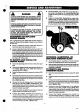
— HOW TO USE YOUR CH9PPER-SHREDDER: BEFORE STARTING 1. Place the shredder on a firm, level surface. 2. Service engine with gasoline and oil as instructed in the separate engine manual packed with your shredder. 3. Insure spark plug wire is attached to spark plug. fA DANGER I A A“ A WARNING A . THE CHIPPEWSHREDDER IS SHIPPED WITHOUT GASOUNEIN THE FUEL TANK AND VERY LlllLE OIL IN THE ENGINE CRANKCASE. DO NOT OPERATE ENGINE U.
-. A r WARNING DANGER A MAKE CERTAIN THE CHIPPER CHUTE GUARD IS IN PLACE. SHOULD THE CHIPPER CHUTE GUARD BECOME WORN OR TORN, REPLACE BEFORE CONTINUING USE. DO NOT DEPOSIT MATERIAL LARGER THAN 1/2” DlAMETER IN THE HOPPER ASSEMBLY. ANY MATERIAL HEAVIER THAN 1/2” SHOULD BE FED INTO THE CHIPPER CHUTE. I I I A ● Leaves and small twigs can be raked into the Hopper assemblyi when the Hopper assembly is rotated to the ground.
DANGER To remove gasoline, run engine “until tankisempty andengine stops. if you do not want to remove gwdine,a gasstabilizer such as STA-BIL may be added to any gasoline left in the tank to minimize gum deposits and ac”ds. If thetankis almost empty, mixstabifiierwith fresh gasoline in aseparatecontainerand add some to the tank. Always follow instructionson stsibiiizer container.Then run engine at feast 10 minutes after etabfIizer is added to allow mixture to reach carburetor.
A “ A DANGER ALWAYS STOP ENGINE AND DISCONNECT SPARK PLUG WIREANDMOVEITAWAY FROM SPARK PLUG BEFORE PERFORMING ANY ADJUSTMENTS OR REPAIRS. . ‘Remove the Made, using a 3/16- alle.rrwvrench(its’ 6) on the outside of the bfade and 1/2- wren~ (iiefiC$ on the impeller assembfy (h@.e,the housing) (See ,HGH-SERV &ADJ). “’”,”, ● Repface or sharperr ‘blade. Re~errible in reverse order making.
.,0 ● Starttheengirk and Iistenftir.anyunusual noise orviiration ~ that could signal im~rope~ installation of the shrei@~ng ~l~e or impeller assern~.nfi:there is an unusudpbiqep vibration, stbp the engine imm@latdy ~d call the factory or contact your tor@ authorized serv.~ ,dealer. Do “not attempt to operate the machine until the problem has been corrected. Aa m Removethe im@dleras$embly(See flG.
/-. , r {, .,:-/, ?. .) .’!.T.-;:.: ,.: .,, ..-: :, .. ... .. . .. . ... . . . .:.,,., :.!, .. . . ... . . .. . ... . .,, . .:,:!i:~;;c,-,..:;:~..,. !, .. < ● - . . .../ CARBURETOR ADJUSTMENT ENGINE SPEED Your engine speed has been fa~ory set. Do not attempt to increase engine speed or it may result in unit damage or personal injury. ff you befieve the engine is running too fast or too slow, take your Chipper/Shredder to the nearest Service Center for repair and adjustment.
,.. . . in ,....,, : PROBLEM POSSfBLE CAUSE (S) I Engine fails to start 1. 2. 3. 4. Fuel tank empty, or stale fuel. Sparkplug wire disconnected. Faufty sparkplug. Dirly fuel filter. (is so equipped) “-1. 2. 3. 4. I Loss of power; operation erratically 1. 2. 3. 4. Sparkplug wire loose. Unit running on CHOKE Blocked fuel line or stafe fuel. Water or dirt in fuel system. 1. 2. 3. 4. , ~ Corrective I ACTfON Fill tank wnh clean, fresh fuel. “” Connect wire to spark pfug.
.. KEY # PART # 10 12 14 180085 996407 15 17 56845 305562 18 327225 18-4 18-6 18-8 18-10 319661 323328 120638 18-12 20 22 24 414072 323839 319660 319659 26 325463 DESCRl~ON ENGINE, 8 HP B&S (SEE ENGINE MANUAL) SCREW, 5/16 -18X 1.75 IN. WASHER, FLAT .328 X .75X .077 NUT, 5/1 6-18 REGHCTRLK KEY, SQUARE .250SQX2.12LG ASSEMBLY, FLAIL BALANCING NON-SERVICEABLE BLADE, CHIPPER SCREW, 5/1 6-24 X 1.00 WASHER, HVSPTLK. ‘ .328 X .60X .09 NUT, 5/1 6-24 REGHCTRLK PIN, FLAIL .50 X 2.81 FLAIL SPACER, SPEC .
i ; / ... . ,, ----- . . . .. ;,..i..$ ,GINE 8HP . . “f ’’:.”‘“m @----l! REF. ENGINE KEY # PART # 60. 62 330088-853 t 20386 64 1498. ’66 1501 68 E 74 57220 330780-853 180077 120386 76 1498 80 82 330781 330782 330571 330289 DESCRIPTION “ PLATE, TANK BRACKET WASHER, FLAT .312X .73X.065 NUT, 5/16-18 REGHEXCTRLK ‘“ WASHER, FIAT .203X .56X,040 SCREW, #12 X .50 BRACKET, GAS TANK SCREW, 5/16-1 8X .751N WASHER, FIAT .312x .73x .
.,- . . . .. . . .. ..,... II PART# KEY # 88. ’90 92 I 305508 326863 323326 II . . ., . . . .. ..4 .. DESCRIPTION TIRE & RIM SEPU 12X3 SPACER, SLEV. 640X1 .00X.688 NUT, PUSH ON 5/8” 327212-32381 5A KEY # 120 125 130 134 136 PART# 328341 330205 325856 330166 326992 DESCRIPllON HOPPER, DEBRIS SCREW, 1/4-20X .5o HANDLE, HOPPER GUARD, WIRE HOPPER RIVET POP .187DIAX .562LG 330216-330217 17 .- .. :::, ,.
.. . . FLAIL HOUSIt4G ASSEMBLY m A . .9 KEY # x 212 214 216 218 220 222 223 225 228 232 234 236 237 238 240 242 244 246 ~ PART# 330108-889 181595 120638 180077 996407 1498 326833 326992 1501 330213-853 180016 120392 1502 996407 1498 330049-889 330205 120392 1502 ~ DESCRIPTION FLAIL HOUSING, ASSEMBLY SCREW, 5/16-24 X .75 WASHER, HVSPTLK .328X .60X .09 SCREW, 5/16-18 X .75 FlATWASHER, .328X .75 k .077 NUT, 5/16-18 REGHEXCTRLK SHROUD COVER, FLAIL RIVET, POP .187 DIA X .562 LG FLATWASHER, .203x.56x.
2HIP c21iuiE ASSEMBLY ,., . . .: .,. .. KEY # 410 414 416 420 422 430 431 432 PART# .31 98*-889 986407 .1498 323333 309235 326834 1501. DESCRIPTION ‘- “ ““ CHUTE, ASSEMBLY CHIPPER WASHER FLAT .328 X .75X .077 NUT, 5/16-18 REGHEXCTRLK GUARD, CHIPPER CHUTE FASTENER, RATCHET HOOD, CHIP CHUTE RIVET, POP (NON SERVICEABLE) (SEE NOTE BELOW) WASHEf+ FIAT .203X .56X .040 L -6C7.. aaaa.nm MOTE: KEY 431, RIVET ISA NON-SERV1CEA8LE ITEM. ORDER 5S686 SCREW, 1 /4-20 X .63 ELTSRMA, 57626 PLATWASHER, .281 Xl .
. . . . ........ CHUTE TUBE & PLATE ASSEMBLY .’
DECALS ., ..,. NSETA KEY # PART# 600 601 602 608 620 628 629 630 330176 330450 330451 330177 402261 402260 330178 330452 DESCRIPTION REFERENCE ONLY REFERENCE ONLY ~ REFERENCE ONLY DECAL, EXPORT, CAUTION GER DECAL, EXPORT, CAUTION ENG/FR DECAL, OPERATOR ENG/FR DECAL, OPERATOR GER DECAL HEARING PROTECTION DECAL, EYE PROTECTION DECAL, EXPORT, DANGERGER DECAL, EXPORT, DANGER ENG/FR i 330802-3228310 21 ,.
rOOIS ASSEMBLY ● ● KEY # I 710 712 PART# I 327243 327789 , DESCRIPTION I TAMPER, CHIP/SHRED GOGGLES, VENTED m 1 326090B-328244A ● .. 308 . .
;,., “a ! BAG COLLECTOR ASSEMBLY . ,, ,, -’ -- ........-7 . ● :0 .@ I KEY #l 810 I PART# 320376 f DESCRIPTION I I BAG, COLLECTOR, DRAWSTRING 32#91A-3282@B 23 .- ..“ “’ .
CASTER WHEEL ASSEMBLY :: g-d .1 ., . KEY # PART # 820 327153-889 822 824 828 830 831 832 833 834 836 838 840 842 844 845 846 848 850 25840 56845 327106 327156-889 325892 706 40677 53806 326863 302270 327874 327875 327157 120396 328713 996416 1499 L ... .. DESCRIPTION CASTER WHEEL SUPPORT FRAME ASSY WASHER, SPRING NUT, 5/16-18 REGHCTRLK PLUG, TUBE CLOSURE 1.25 DIA CASTER WHEEL YOKE ASSY WASHER, PLASTIC, .06X .625X 1.5 ZERK, GREASE F17TING WASHER, FIAT .640X 1.25 X.06 WASHER, FLAT .632X 1.11 X.
,. ● ~,:l,l~q]q,~ . ., .“. , .:. ? . . . . ., $,., ’O; .,. ... ! ,. The following pages illustrate optional equipment that can be added to your Chipper/Shredder. If your unit is already equipped with these items, use the information to order service parts. ● ● S800-00 VACUUM HOSE KIT 10 foot hose will easily vacuum leaves and debris in hard to reach places. ● S800-01 HITCH BAR KIT To tow the Chipper/Shredder behind your tractor. For units equipped w/caster wheels.
THIS W? INCLUDES THE.FOLLOWING: Your vacuum hose attachment comes completely assembled and ready to use with your Chipper/Shredder. TOOLS REQUIRED FOR ASSEMBLY: cwurERciocKwlsE 1- Wire Cutters (or knife) TO INSTALL VACUUM . ● ● HOSE Remove hose attachment from carton and remove the (2) straps holding the handle to the tube. \ Lay the hose attachment out straght on the ground to remove any twist in the hose.
. ..’. ) ,... .: :’., .. ● NOTE: Hitch bar kit must be used with c~ter wheel kti (See sepsrate Instruction sheet supplied with caster wheel for caster wheel installation). Remove draw bar kii pivot bracket (#857), tongue (#862) and parts bag from the carton. TOOLS REQUIRED FOR ASSEMBLY: ● Position pivot bracket as shown in Fw; 1, aligning .{2)” holes in pivot bracket with(2) holes in front of the engine plate. ● Attach pivot bracket to engine piate using the 5/1618x.75 inch screws (#858), .31x.
f-t ‘ ..1 . .. ... . . ● TH9S K9TlNCLUDES THE FOLLOW#NG Your caster wheel kn times completely assembled and ready to attach to your Chipper/Shredder. TOOLS REQUIRED FOR ASSEMBLY: 1- 1/2”Wrench TO 9NSTALL CASTER WHEEL: P T WARNING: TO REDUCE THE POTENTfA1. FOR ANY INJURY, COMPLY WITH THE SAFETY iNSTRUCTIONS FOUND IN YOUR CHIPPER/ SHREDDER OWNER’S MANUAL. iNSTALLATION OF ATTACHMENTS SHOULD BE DONE ONLY WHEN ENGINE IS STOPPED. 4 A k . REMOVE CASTER WHEEL ASSEMBLY AND PARTS BAG FROM CARTON .
.,, ... . . . . . -. .,. .. . ......... .... TOOLS, ,REQU[RED.:FOR ASSEMBLY:” 1 -1/2” WrenA ““ ,’ “’ ~ .. ● ‘ 10 iNSTAL&TOWING KIT: . A WARNING: To reduce the potential for any injury, comply with the safety Instructions found in your tractor and chipper/shredder owner’s manual. . ... . . . . .. ,., ,.. : ,,,. .....’.. ‘..’ .:, . . Install clevis pin (#667) and hairpin (#@68~into’desirsd’ hole positiin (See. Fig. 1). Position “#1 is used when towing the Chipper/Shredder.
TO INSTALL CASTER WHEEiJ r A ● WARNING: TO REDUCE THE POTENTIAL FOR ANY INJURY, COMPLY WITH THE SAFEN iNSTRUCTIONS’ FOUND IN YOUR CHIPPER/ SHREDDER OWNER’S MANUAL. iNSTALLATION OF ATTACHMENTS SHOULD BE DONE ONLY WHEN ENGINE IS STOPPED. REMOVE CASTER WHEEL ASSEMBLY AND PARTS BAG FROM CARTON . With Chipper/Shredder on a level surface, carefully tilt the unit forward to access the leg support. .