
Owner`s manual


A “
DANGER
A
ALWAYS STOP ENGINE AND DISCONNECT SPARK
PLUG WIREANDMOVEITAWAY FROM SPARK PLUG
BEFORE PERFORMING ANY ADJUSTMENTS OR RE-
PAIRS.
WHEN CLEANIN~ REPAIRfNG OR INSPECTING YOUR
CHIPPEFUSHREDDER MAKE CERTAIN ALL MOVING
PARTS HAVE STOPPED.
TO REDUCE THE RISK OF INJURY, ALWAYS WEAR
HEAVY GLOVES WHEN HANDUNG THE CUITING
BLADES. THE CUTllNG EDGES ARE SHARP AND
CAN CAUSE SEVERE INJURY.
s
d
Sharpening OR REPLACING
CHIPPER BLADES:
Over a perkxf of time, the cutting blade will dull. Sharpen or
replace the blade when the chipper no Iongercuts as efficiently
as’when new.
● Discard a cracked or severely nicked blade because it
could break apart and cause personal injury.
● Sharpen abladethat isdullorthat has only minor nicks. The
blade is made from tempered steel and is extremely hard -
do not attempt to sharpen with a hand file. We recommend
that youtakethebladeto aprofessiortal sharpening service
for proper sharpening. All grinding must be done flat and
uniform along the beveled edge oniy, being sureto maintain
the original 45° cutting angle.
TO REMOVE AND INSTALL THE
CHIPPER BLADE:
Disconnect epa~ plug wire and move it away from spark
plug.
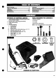
Remove the Chipper chute by removing three(3) hex nuts
and washers (iems B). A 1/2” socket with extension is
required (See FIG.-3 ASSY).
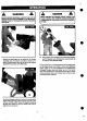
Rotatethe Hopparassemblytotheground as shown in FIG.
3-OP.
Remove the three(3) hex focknuts (iem A) and flatwashers
(iem B) from the housing studserts and carefully separate
the Hopper assembly from the remainder of the unit (See
FIG. 2-SERV. & ADJ.)
Remove the three (3) bushings (item C) and stationary
plate (iem D). (See FIG. 2-SERV. & ADJ) NOTE: When
reassembling, make certain the opening of the stationary
plate istoward the bottom of the unit and the offset, isfacing
toward the impeller assembly.~
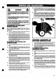
Rotate the impeller assembly by hand until you locate the
Chipper blade in the Chipper chute ~pening.
Prevent the impeller assembly from turning in a
counterclockwise direction by wedging a block of wood
between one of the fan blades and the wall of the housing
or, insert a thick, hardwood dowel (item A) through the slot
below the blade and into the Chipper chute opening in the
wall of the housing. (See FIG. 1-SERV & ADJ).
.
,..
--
,..
. ‘Remove the Made, using a 3/16- alle.rrwvrench(its’ 6) on
the outside of the bfade and 1/2- wren~ (iiefiC$ on the
impeller assembfy (h@.e,the housing) (See ,HGH-SERV
&ADJ). “’”,”,
● Repface or sharperr ‘blade. Re~errible in reverse order
making. certain to install the “,bladb with the s@rp edge
faang away fromtheimpellerassembij and~~ngtoward
the sfotin the impeller assembfy. Tmhten Ioclmutssecurefy
(i using a torque wrench, tighten @mrts to 20 ft-lbs). -
.?o -
.6.
,,
,
:
RMRSING, SHARPENING, OR
REPLACING SHREDDER BLAD~
● The shredding blade is reversible and can be reversed
before any sharpening shoufd need to be pwformed.
● After both sides of the blade have become dull, nicked, etc.
to the point of reduang performance, the blade needs to be
sharpened orreplaced.
TO REMOVE AND INSTALL -
SHREDDING BLADB
Disconnect spark plug wire and move it away from spark
plug.
Rotatethe Hopperassemblytotheground asshownin flG
3-OP.
Remove the three (3) hex locknuts (iem A) and flatwashers
(iem B)from the housing studserts and carefully separate
the Hopper assembly from the remainder of the unit (See
FIG. 2- SERV & ADJ.).
Remo#e the three (3) bushings (item C) and stationary
plate”(item f)) (See FIG. 2- SERV.& ADJ.) (NOTE: When
reassembling, make certain the opening of the stationary
plate istowardthe bottom of the unit and the offset, isfaang
toward the impeller assembly).
Prevent the impeller assem,bly from turning in a
counterclockwise direction by wedging a block of wood
between one of the fan blades and the wall of the housing.
..
297
.