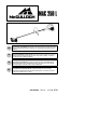
GB FR DE ES INSTRUCTION MANUAL IMPORTANT INFORMATION: Please read these instructions carefully and make sure you understand them before using this unit. Retain these instructions for future reference. MANUEL D’INSTRUCTIONS RENSEIGNEMENTS IMPORTANTS: Avant d’utiliser cet appareil, veuillez lire atentivement les instructions et assurez--vous de les avoir comprises. Conservez les instructions pour référence ultérieure.
IDENTIFICATION (WHAT IS WHAT?) 18 2 4 6 7 9 8 12 1 10 16 21 17 11 13 19 15 3 14 20 1. 2. 3. 4. 5. 6. 7. 8. 9. 10. 11. 22 Fuel tank Loop handle ON/STOP switch Shoulder strap clamp Shoulder strap Trimmer head Line limiter blade Shield Shaft J--handle Blade 12. 13. 14. 15. 16. 17. 18. 19. 20. 21. 22. Throttle trigger Throttle lock--out Starter handle Fuel cap Primer bulb Choke lever Muffler Wrench Hex wrench Instruction manual Transport guard 5 IDENTIFICATION OF SYMBOLS A. D. F. I. B.
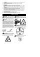
A. B. C. D. E. F. G. H. I. J. K. WARNING! This brushcutter can be dangerous! Careless or improper use can cause serious or even fatal injury. Read and understand the instruction manual before using the brushcutter. Always use: Ear protection, eye protection, head protection, boots, and gloves. DANGER! Blade can thrust violently away from material it does not cut. Blade thrust can cause amputation of arms or legs. Keep people and animals 15 meters away.
WARNING: The blade continues to spin after the throttle is released or, engine is turned off. The coasting blade can throw objects or seriously cut if accidentally touched. Stop the blade by contacting the right hand side of the coasting blade with material already cut. Stop coasting blade by contact with cut material. OPERATOR SAFETY S Dress properly. Always wear safety glasses or similar eye protection when operating, or performing maintenance, on your unit (safety glasses are available).
S Keep all parts of your body away from blade, trimmer head, and muffler when engine is running. A hot muffler can cause serious burns. S Cut from your left to your right. Cutting on right side of the shield will throw debris away from the operator. S Use only in daylight or good artificial light. S Use only for jobs explained in this manual. TRANSPORTING AND STORAGE S Allow the engine to cool; secure unit before storing or transporting in vehicle.
HARNESS ADJUSTMENT FOR BALANCE 15 cm below waist ASSEMBLY OF SHOULDER STRAP Proper shoulder strap and handlebar adjustments must be made with the engine completely stopped before using unit. 1. Insert your right arm and head through the shoulder strap and allow it to rest on your left shoulder. Make sure the hook is to the right side of your waist. NOTE: A one-half twist is built in the shoulder strap to allow the strap to rest flat on the shoulder. 2.
blade nut by turning clockwise. Remove the screwdriver. Remove both washers and blade. To remove metal shield, loosen and remove the four mounting screws. See ATTACHING THE METAL SHIELD and INSTALLATION OF THE METAL BLADE for illustrations. Be sure to store all parts and instructions for future use. ATTACHING THE PLASTIC SHIELD AND TRIMMER HEAD WARNING: The shield must be properly installed.
INSTALLATION OF THE METAL BLADE NOTE: Make sure all parts are in place as il- WARNING: Wear protective gloves when handling or performing maintenance on the blade to avoid injury. The blade is sharp and can cut you even when it is not moving. WARNING: Do not use any blades, or fastening hardware other than the washers and nuts shown in the following illustrations. These parts must be provided by McCulloch and installed as shown below.
OPERATION WARNING: Be sure to read the fuel information in the safety rules before you begin. If you do not understand the safety rules, do not attempt to fuel your unit. Contact an authorised service dealer. STARTING A COLD ENGINE (or a warm engine after running out of fuel) Starting position FUELING ENGINE WARNING: Remove fuel cap slowly when refueling. This engine is certified to operate on unleaded petrol. Before operation, petrol must be mixed with a good quality 2-cycle air-cooled engine oil.
8. Pull starter rope sharply until engine runs, but no more than 6 pulls. If the engine doesn’t start after 6 pulls (at the HALF CHOKE position), move the choke lever to the FULL CHOKE position and press the primer bulb 6 times. Squeeze and hold the throttle trigger and pull the starter rope 2 more times. Move the choke lever to the HALF CHOKE position and pull the starter rope until the engine runs, but no more than 6 pulls. NOTE: If engine still doesn’t start, it is probably flooded.
Tip of line does the cutting. Line crowded into work area. Right Mowing Wrong S The line will easily remove grass and weeds from around walls, fences, trees and flower beds, but it also can cut the tender bark of trees or shrubs and scar fences. S For trimming or scalping, use less than full throttle to increase line life and decrease head wear, especially: S During light duty cutting. S Near objects around which the line can wrap such as small posts, trees or fence wire.
S Cut only grass, weeds, and woody brush up to 1 cm in diameter with the weed blade. Do not let the blade contact material it cannot cut such as stumps, rocks, fences, metal, etc., or clusters of hard, woody brush having a diameter greater than 1 cm. S Keep the blade sharp. A dull blade is more likely to snag and thrust. S Cut only at full throttle. The blade will have maximum cutting power and is less likely to bind or stall. S “Feed” the blade deliberately and not too rapidly.
REPLACE SPARK PLUG Button Air Filter Air Filter Cover Replace the spark plug each year to ensure the engine starts easier and runs better. Set spark plug gap at 0,6 mm. Ignition timing is fixed and nonadjustable. 1. Twist, then pull off spark plug boot. 2. Remove spark plug from cylinder and discard. 3. Replace with Champion RCJ-6Y spark plug and tighten securely with a 19 mm socket wrench. 4. Reinstall the spark plug boot. SERVICE AND ADJUSTMENTS REPLACING THE LINE 1.
Make adjustments with the unit supported so the cutting attachment is off the ground and will not make contact with any object. Hold the unit by hand while running and making adjustments. Keep all parts of your body away from the cutting attachment and muffler. Idle Speed Screw Idle Speed Adjustment Allow engine to idle. Adjust speed until engine runs without trimmer head moving or spinning (idle speed too fast) or engine stalling (idle speed too slow).
TROUBLESHOOTING TABLE WARNING: Always stop unit and disconnect spark plug before performing all of the recommended remedies below except remedies that require operation of the unit. TROUBLE CAUSE Engine will not start. 1. ON/STOP switch in STOP 1. Move ON/STOP switch to ON position. position. 2. Engine flooded. 2. See “Starting a Flooded Engine” in Operation Section. 3. Fuel tank empty. 3. Fill tank with correct fuel mixture. 4. Spark plug not firing. 4. Install new spark plug. 5. Fuel not reaching 5.
DECLARATION OF CONFORMITY EC Declaration of Conformity (Only applies to Europe) We, Husqvarna Outdoor Products Italia, S.p.A., Valmadrera, Italy.
TECHNICAL DATA SHEET MODEL: Mac 250 L Blade Trimmer ENGINE 3 25 25 Displacement, cm Maximum engine power, measured in accordance with ISO 8893, kW 0,7 0,7 Catalytic converter muffler Yes Yes ENGINE ROTATIONAL SPEEDS At maximum engine power, rpm 8000 8000 Maximum rotational frequency of the spindle 10000 10000 Engine speed at recommended maximum spindle rotational frequency 7400 7400 Recommended speed idling, rpm 3000 3000 FUEL AND LUBRICATION SYSTEM 340 340 Fuel tank volume capacity, cm3 Fuel consumption at