MC621 Owner's Manual
CONGRATULATIONS on your purchase of a new snow thrower. It has been designed, engineered and manufactured to give best possible dependability and performance. Should you experience any problem you cannot easily remedy, please contact your nearest authorized service center. We have competent, well-trained technicians and the proper tools to service or repair this unit. Please read and retain this manual. The instructions will enable you to assemble and maintain your snow thrower properly.
2. Exercise extreme caution when operating on or crossing gravel drives, walks, or roads. Stay alert for hidden hazards or traffic. 3. After striking a foreign object, stop the engine (motor), disconnect the cord on electric motors, thoroughly inspect the snow thrower for any damage, and repair the damage before restarting and operating the snow thrower. Remove key. 4. If the unit should start to vibrate abnormally, stop the engine (motor) and check immediately for the cause.
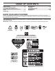
TABLE OF CONTENTS SAFETY RULES ........................................................ 2-3 PRODUCT SPECIFICATIONS ...................................... 3 CUSTOMER RESPONSIBILITIES................................ 3 SAFETY AND INSTRUCTIONAL DECALS ................. 4 SETUP........................................................................ 5-6 OPERATION ............................................................ 7-11 MAINTENANCE ..................................................... 11-15 STORAGE .....
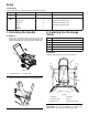
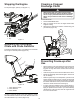
Setup Loose Parts Use the chart below to verify that all parts have been shipped. Procedure 1. 2. Description Qty. Use No parts required – Unfold the handle. Carriage bolts Flange nuts Washers Knob Chute Deflector 5 4 2 1 1 1 Install the discharge chute. Install the discharge chute. Install the discharge chute. Install the discharge chute. 1. Unfolding the Handle 2. Installing the Discharge Chute Procedure 1.
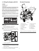
3. Filling the Engine with Oil Product Overview ENGINE See engine manual. 13 LUBRICATION Use only high quality detergent oil rated with API service classification SG–SL. Select the oil's SAE viscosity grade according to your expected operating temperature. NOTE: Although multi-viscosity oils (5W30, 10W30 etc.) improve starting in cold weather, these multi-viscosity oils will result in increased oil consumption when used above 32°F.
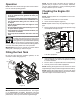
Operation NOTE: For best results, purchase only the quantity of gasoline that you expect to use in 30 days. Otherwise, you may add fuel stabilizer to newly purchased gasoline to keep it fresh for up to 6 months. NOTE: Determine the left and right sides of the machine from the normal operating position. Checking the Engine Oil Level • Gasoline is extremely flammable and explosive. A fire or explosion from gasoline can burn you and others.
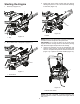
Starting the Engine 3. Firmly push in the primer 3 times with your thumb, holding the primer in a for a second before releasing it each time (Figure 12). 1. Push key in (Figure 10). 1 1 Figure 12 1. Key 1. Primer Figure 10 NOTE: Remove your glove when you push in the primer so that air cannot escape from the primer hole. IMPORTANT: Do not use the primer or the choke if the engine has been running and is hot. Excessive priming may flood the engine and prevent it from starting. 2.
Engaging the Auger Blades The electrical cord can become damaged, causing a shock or fire. Thoroughly inspect the electrical cord before plugging it into a power source. If the cord is damaged, do not use it to start the snowthrower. Replace or repair the damaged cord immediately. Contact an Authorized Service Dealer for assistance. To engage the auger blades, hold the control bar against the handle (Figure 15). 1 1 Figure 15 1. Control bar Disengaging the Auger Blades Figure 14 1.
Stopping the Engine Clearing a Clogged Discharge Chute To stop the engine, pull key out (Figure 17). Hand contact with the rotating auger blades inside the discharge chute is the most common cause of injury associated with snow throwers. Never use your hand to clean out the discharge chute. To clear the chute: 1. SHUT THE ENGINE OFF! 2. Wait 10 seconds to be sure the auger blades have stopped rotating. 3. Always use a clearing tool at least 15 inches long, not your hands (Figure 19). 1 1.
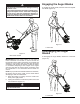
Operating Tips • The auger blades can throw stones, toys, and other foreign objects and cause serious personal injury to the operator or to bystanders. • Keep the area to be cleared free of all objects that the auger blades could pick up and throw. • Keep all children and pets away from the area of operation. • Do not operate snow thrower if weather conditions impair visibility. Throwing snow during a heavy, windy snowstorm can blind you and be hazardous to the safe operation of the snow thrower.
Adjusting the Control Cable Adjusting the Control Cable Checking the Control Cable 1. With the control bar disengaged, unhook and move the control cable to the highest position. (Figure 21). Release the control bar to remove the slack in the control cable (Figure 20). 1 Position 2 2 3 1 Position 1: Default position (Lower Hole as shown in illustration) Figure 21 1. Control bar 2. Adjuster link 3. Cable positions Figure 20 1.
Changing the Engine Oil 7. Clean around the oil filler cap/dipstick (Figure 24). 8. Unscrew the oil fill cap/dipstick and remove it (Figure 24). 9. With the snowthrower in the operating position, carefully pour oil into the oil fill hole until "Full" on the fill cap/dipstick line (Figure 26). Run the engine a few minutes before changing the oil to warm it. Warm oil flows better and carries more contaminants. Max fill: 18 oz. (0.
Servicing the Spark Plug 5. 6. 7. 8. Remove the oil fill cap. Remove the shroud assembly (Figure 28). Install the oil fill cap. Disconnect the spark plug wire from the spark plug (Figure 29). 9. Clean around the spark plug. 10. Remove the spark plug from the cylinder head. Use a NGK BPR6ES, Champion RN9YC, or BOSCH WR6DC spark plug or equivalent. 1. Stop the engine and wait for all moving parts to stop. 2. Rotate the discharge chute so that it faces forward. 3.
Replacing the Drive Belt 4. Install the new drive belt, routing it as shown in (Figure 32). NOTE: Route the new drive belt first around the engine pulley, then the idler pulley, and finally around the drive pulley while pressing down on the front of the idler arm. (Figure 32). If drive belt becomes worn, oil-soaked, excessively cracked, frayed, or otherwise damaged, replace the belt. 1. Remove the drive side cover by removing the six screws as shown in (Figure 31). 4 5 5.
Storage ENGINE OIL Drain oil (with engine warm) and replace with clean engine oil. (See “Changing the Engine Oil” section of this manual). Storing the Snowthrower CYLINDER 1. Remove spark plug. 2. Pour one ounce (29 ml) of oil through spark plug hole into cylinder. 3. Pull recoil starter handle slowly a few times to distribute oil. 4. Replace with new spark plug. Immediately prepare your snow thrower for storage at the end of the season or if the unit will not be used for 30 days or more.
Troubleshooting See appropriate section in manual unless directed to an authorized service center/department. PROBLEM Does not start CAUSE 1. Fuel shut-off valve (if so equipped) in OFF position. 2. Safety ignition key is not inserted. 3. Out of fuel. 4. Throttle in STOP position (or ON/OFF switch is OFF). 5. Choke in OFF position. 6. Primer not depressed. 7. Engine is flooded. 8. Spark plug wire is disconnected. 9. Bad spark plug. 10. Stale fuel. 11. Water in fuel. CORRECTION 1.
REPAIR PARTS SNOW THROWER - - MODEL NUMBER MC621 (96182000500) CHUTE ASSEMBLY 1 4 4 2 2 4 5 18 3 6 19 19 7 17 6 8 20 15 16 9 10 15 11 21 SSST-Chute asm_5 19 4 NOTE: All component dimensions given in U.S. inches. 1 inch = 25.4 mm IMPORTANT: Use only Original Equipment Manufacturer (O.E.M.) replacement parts. Failure to do so could be hazardous, damage your snow thrower and void your warranty.
REPAIR PARTS SNOW THROWER - - MODEL NUMBER MC621 (96182000500) CHUTE ASSEMBLY KEY NO. PART NO. QTY DESCRIPTION 1 532 43 48-77 1 CHUTE.RATCHETING.PLASTIC.W/GRV 2 532 43 76-40 2 PLATE.CHUTE.RETAINER 3 532 43 76-35 1 PLATE.CHUTE.BASE 4 817 41 13-12 6 BOLT.HEX.WSH.HD.13-16 X 3/4 5 532 43 76-42 1 HANDLE.CHUTE.MS428 6 873 97 05-00 4 NUT.LOCK.HX.W/INS 5/16-18 UNC PL 7 532 43 48-79 1 SPRING.RATCHET.ARM 8 532 08 13-28 1 BOLT.SHOULDER.1/4-20 UNC X .94 9 532 43 48-78 1 ARM.
REPAIR PARTS SNOW THROWER - - MODEL NUMBER MC621 (96182000500) HANDLE ASSEMBLY 1 2 5 4 3 5 6 SSST-Handle asm_1 KEY NO. 1 PART NO. 532 43 76-47 QTY 1 DESCRIPTION BAIL.HANDLE.PAINT.MS431 2 532 43 76-46 1 HANDLE.PNT.UPPER.SSST 3 532 43 48-06 1 CONTROL.CABLE 4 532 19 19-38 2 KNOB.HANDLE.BLACK 5 532 19 15-74 2 BOLT.HANDLE.BLACK PATCHED 6 532 14 50-06 1 CLIP.PUSH-IN.HINGED NOTE: All component dimensions given in U.S. inches. 1 inch = 25.
REPAIR PARTS SNOW THROWER - - MODEL NUMBER MC621 (96182000500) AUGER ASSEMBLY 2 3 1 10 11 4 14 7 56 13 9 1 12 8 9 11 12 5 5 4 13 6 10 11 SSST-Auger asm_1 7 KEY NO. PART NO. QTY 1 DESCRIPTION 1 872 11 04-07 12 BOLT.CARRIAGE 2 532 43 76-20 1 PIN.ROLL.3/16 X 1-1/4 3 532 19 96-87 1 BOLT.1/4-20.1.50" 4 532 43 76-18 2 PLATE.CENTER.BLADE 5 532 13 20-04 13 HEX.NUT.1/4-20 NYLON LOCKING 6 819 09 10-16 8 WASHER 9/32 X 5/8 X 16 GA. 7 532 43 74-59 2 BLADE.
REPAIR PARTS SNOW THROWER - - MODEL NUMBER MC621 (96182000500) SHROUD ASSEMBLY 16 5 14 6 1 7 17 4 10 15 17 17 3 2 10 8 9 10 12 11 SSST-Shroud asm_7 NOTE: All component dimensions given in U.S. inches. 1 inch = 25.4 mm IMPORTANT: Use only Original Equipment Manufacturer (O.E.M.) replacement parts. Failure to do so could be hazardous, damage your snow thrower and void your warranty.
REPAIR PARTS SNOW THROWER - - MODEL NUMBER MC621 (96182000500) SHROUD ASSEMBLY KEY NO. PART NO. QTY DESCRIPTION 1 532 43 76-27 1 COVER.NON-DRIVE.SIDE.MS428 2 532 43 76-30 1 COVER.DRIVE.SIDE.MS428 3 532 43 76-34 1 TOP.COVER 4 532 43 02-20 1 CAP.ASM.FUEL.2.25"FR.N/CB.E10 5 532 43 62-35 1 BULB.PRIMER 6 532 43 54-07 1 KEY HOUSING 7 532 43 76-48 1 TOP.REAR.COVER 8 532 43 76-31 1 PLATE.EXHAUST.PNT. 9 817 41 13-12 2 SCREW 10 817 67 04-12 12 SCREW.HEXWSH.THDROL.
REPAIR PARTS SNOW THROWER - - MODEL NUMBER MC621 (96182000500) FRAME ASSEMBLY 11 1 10 4 3 12 2 8 3 12 5 6 4 6 9 SSST-Frame asm_3 7 NOTE: All component dimensions given in U.S. inches. 1 inch = 25.4 mm IMPORTANT: Use only Original Equipment Manufacturer (O.E.M.) replacement parts. Failure to do so could be hazardous, damage your snow thrower and void your warranty.
REPAIR PARTS SNOW THROWER - - MODEL NUMBER MC621 (96182000500) FRAME ASSEMBLY KEY NO. PART NO. QTY DESCRIPTION 1 532 43 48-56 1 LCT.ENGINE 2 532 43 76-06 1 FRAME.WELDMENT 3 532 43 76-16 2 WHEEL.7X1.5.DMD.GS.3SPK.MS428 4 532 43 54-17 2 NUT.PUSH.AXLE.0.5IN 5 532 43 55-78 2 SCREW. 5/16-24 X 2.00"HHCS 6 532 15 04-06 2 BOLT.ENG. 3/8-16 X 1.280 7 532 19 17-30 3 NUT.HEX.FLANGE.1/4-20.CTR.LOCK 8 872 14 04-05 3 BOLT.RDHD.SQNK.1/4-20 UNC X 5/8 9 532 43 55-35 1 PLATE.
50 5 27 4 37 30 31 58 34 49 16 47 29 25 33 39 38 55 44 56 Included with part# 40 41 10 12 40 22A 22 36 32 23 45 59 42 26 26A 15 21 1 20 20A 3 28 6 2 18 19 46 13 8 11 48 Electric Start Only 17
REFERENCE # 1 2 3 4 5 6 7 8 10 11 12 13 15 16 17 18 19 20 20A 21 22 22A 23 25 26 26A 27 28 29 30 31 32 33 34 36 37 38 38A 39 40 41 42 44 45 46 47 48 49 50 54 55 56 58 59 208cc SERVICE KIT BREAKDOWN PART DESCRIPTION HEATER BOX ASSY SHIELD, HEATER BOX SNOW MUFFLER ASSY SNOW FUEL TANK ASSY OVERSIZED FUEL TANK CAP (CLICK STYLE) SNOW CARBURETOR ASSY (INCLUDES BRACKET, SPACER, AND NUTS) SNOW CHOKE LEVER, CARBURETOR (NOT SHOWN) FUEL PRIMER BULB WITH HOSE ELECTRIC STARTER ASSY KEY SWITCH ASSY CDI BOX ON/OFF SWITCH
REPAIR PARTS SNOW THROWER - - MODEL NUMBER MC621 (96182000500) DRIVE ASSEMBLY 1 3 7 4 2 5 8 6 11 10 9 12 SSST-Drive asm_3 KEY NO. PART NO. 13 QTY DESCRIPTION 1 532 43 48-60 1 SPACER.ENGINE.CRANK 2 532 43 45-02 1 KEEPER.ENGINE.BELT 3 532 42 64-90 1 PULLEY.ENG.TRACTION.3/4 4 532 85 10-74 1 WASHER.HARDEN 5 532 43 72-61 1 BELT-V.TRACTION 6 532 43 08-17 1 SCREW.CAP.SCHD.3/8-24 X 1.25 7 532 43 48-59 1 SPRING.IDLER.PULLEY.RETURN 8 532 43 76-09 1 ARM.IDLER.PNT.
SERVICE NOTES 27
LIMITED WARRANTY The Manufacturer warrants to the original consumer purchaser that this product as manufactured is free from defects in materials and workmanship. For a period of two (2) years from date of purchase by the original consumer purchaser, we will repair or replace, at our option, without charge for parts or labor incurred in replacing parts, any part which we find to be defective due to materials or workmanship. This Warranty is subject to the following limitations and exclusions. 1.