MCRT55 Owner's Manual
SAFETY RULES Safe Operation Practices for Walk-Behind Powered Rotary Tillers TRAINING • • • • Read the Manual carefully. Be thoroughly familiar with the controls and the proper use of the equipment. Know how to stop the unit and disengage the controls quickly. Never allow children to operate the equipment. Never allow adults to operate the equipment without proper instruction. Keep the area of operation clear of all persons, particularly small children, and pets.
PRODUCT SPECIFICATIONS GASOLINE CAPACITY: Unleaded Regular 3 Quarts (2.8L) OIL (API-SF-SJ): (Capacity: 19 oz./1.3L) SAE 30 (Above 40°F/4°C) SAE 3w-30 (Below 40°F/4°C) SPARK PLUG : (GAP: .030"/0.76mm) Champion RJ19LM or J19LM CUSTOMER RESPONSIBILITIES • • Read and observe the safety rules. Follow a regular schedule in maintaining, caring for and using your tiller. • Follow instructions under “Maintenance” and “Storage” sections of this Owner’s Manual.
ASSEMBLY Your new tiller has been assembled at the factory with exception of those parts left unassembled for shipping purposes. To ensure safe and proper operation of your tiller all parts and hardware you assemble must be tightened securely. Use the correct tools as necessary to insure proper tightness. TOOLS REQUIRED FOR ASSEMBLY FRONT A socket wrench set will make assembly easier. Standard wrench sizes are listed.
ASSEMBLY UNPACKING CARTON (See Fig. 2) CAUTION: Be careful of exposed staples when handling or disposing of cartoning material. HANDLE ASSEMBLY "UP" POSITION TIGHTEN HANDLE LOCK LEVER TO HOLD IMPORTANT: WHEN UNPACKING AND ASSEMBLING TILLER, BE CAREFUL NOT TO STRETCH OR KINK CABLES. • • • • • • While holding handle assembly, cut cable ties securing handle assembly to top frame. Let handle assembly rest on tiller. Remove top frame of carton. Slowly ease handle assembly up and place on top of carton.
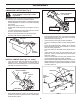
ASSEMBLY INSERT CABLE CLIP (See Fig. 6) • Insert plastic cable clip into hole on the back of handle column. Push cables into clip. ATTACH THIS END TO SHIFT LEVER INDICATOR HAIRPIN CLIP HANDLE COLUMN SHIFT ROD SHIFT LEVER INDICATOR CABLES SHIFT ROD CABLE CLIP FIG. 6 CONNECT SHIFT ROD (See Fig. 7) • • Insert end of shift rod farthest from bend into hole of shift lever indicator. Insert hairpin clip through hole of shift rod to secure with bend of clip on right side. FIG.
OPERATION KNOW YOUR TILLER READ THIS OWNER'S MANUAL AND SAFETY RULES BEFORE OPERATING YOUR TILLER. Compare the illustrations with your tiller to familiarize yourself with the location of various controls and adjustments. Save this manual for future reference. These symbols may appear on your Tiller or in literature supplied with the product. Learn and understand their meaning. DRIVE CONTROL BAR THROTTLE CONTROL SHIFT LEVER SHIFT LEVER INDICATOR DEPTH STAKE LEVELING SHIELD RECOIL STARTER HANDLE FIG.
OPERATION The operation of any tiller can result in foreign objects thrown into the eyes, which can result in severe eye damage. Always wear safety glasses or eye shields before starting your tiller and while tilling. We recommend a wide vision safety mask for over spectacles or standard safety glasses. 00155 HOW TO USE YOUR TILLER DEPTH STAKE (See Fig. 10) The depth stake can be raised or lowered to allow you more versatile tilling and cultivating, or to more easily transport your tiller.
OPERATION TURNING • • • • • • • Release the drive control bar. Move throttle control to “SLOW” position. Place shift lever indicator in “F” (forward) position. Tines will not turn. Lift handle to raise tines out of ground. Swing the handle in the opposite direction you wish to turn, being careful to keep feet and legs away from tines. When you have completed your turn-around, release the drive control bar and lower handle. Place shift lever in till position and move throttle control to desired speed.
OPERATION • When starting engine for the first time or if engine has run out of fuel, it will take extra pulls of the recoil starter to move fuel from the tank to the engine. • Make sure spark plug wire is properly connected. • Move shift lever indicator to “N” (neutral) position. • Place throttle control in “FAST” position. • Turn fuel shut-off valve to 1/4 turn to OPEN position. • Push stop switch to “ON” position. • Move choke control to full “CHOKE” position.
FILL IN DATES AS YOU COMPLETE REGULAR SERVICE BE FO MAINTENANCE SCHEDULE RE EA EV CH ER US Y5 E HO EV ER UR Y2 S 5H EV O ER UR Y5 S 0 EV HO ER UR YS S EA SO N MAINTENANCE SERVICE DATES Check Engine Oil Level Change Engine Oil 1,2 Oil Pivot Points Inspect Spark Arrester / Muffler Inspect Air Screen Clean or Replace Air Cleaner Cartridge 2 Clean Engine Cylinder Fins Replace Spark Plug RH Gear Case Grease Fitting (1oz.
MAINTENANCE Disconnect spark plug wire before performing any maintenance (except carburetor adjustment) to prevent accidental starting of engine. Prevent fires! Keep the engine free of grass, leaves, spilled oil, or fuel. Remove fuel from tank before tipping unit for maintenance. Clean muffler area of all grass, dirt, and debris. Do not touch hot muffler or cylinder fins as contact may cause burns. ENGINE LUBRICATION Use only high quality detergent oil rated with API service classification SG-SL.
MAINTENANCE MUFFLER COOLING SYSTEM (See Fig. 19) Do not operate tiller without muffler. Do not tamper with exhaust system. Damaged mufflers or spark arresters could create a fire hazard. Inspect periodically and replace if necessary. If your engine is equipped with a spark arrester screen assembly, remove every 50 hours for cleaning and inspection. Replace if damaged. Your engine is air cooled. For proper engine performance and long life keep your engine clean.
SERVICE AND ADJUSTMENTS CAUTION: Disconnect spark plug wire from spark plug and place wire where it cannot come into contact with plug. TILLER TO ADJUST HANDLE HEIGHT (See Fig. 20) Select handle height best suited for your tilling conditions. Handle height will be different when tiller digs into soil. • First loosen handle lock lever. • Handle can be positioned at different settings between “HIGH” and “LOW” positions. • Retighten handle lock lever securely after adjusting.
SERVICE AND ADJUSTMENTS TO REPLACE GROUND DRIVE BELT (See Figs. 22 and 23) • • • • • • • GROUND DRIVE BELT ADJUSTMENT (See Fig. 23) Remove belt guard (See “TO REMOVE BELT GUARD” in this section of this manual). Remove old belt by slipping off engine pulley first then remove from transmission pulley. Place new belt in groove of transmission pulley and into engine pulley. BELT MUST BE IN GROOVE ON TOP OF IDLER PULLEY. NOTE POSITION OF BELT TO GUIDES. Check belt adjustment as described below.
SERVICE AND ADJUSTMENTS • TINE REPLACEMENT (See Figs. 24, 25 and 26) CAUTION: Tines are sharp. Wear gloves or other protection when handling tines. • A badly worn tine causes your tiller to work harder and dig more shallow. Most important, worn tines cannot chop and shred organic matter as effectively nor bury it as deeply as good tines. A tine this worn needs to be replaced.
SERVICE AND ADJUSTMENTS ENGINE TO ADJUST CARBURETOR Maintenance, repair, or replacement of the emission control devices and systems, which are being done at the customers expense, may be performed by any nonroad engine repair establishment or individual. Warranty repairs must be performed by an authorized engine manufacturer's service outlet. The carburetor has been preset at the factory and adjustment should not be necessary.
STORAGE Immediately prepare your tiller for storage at the end of the season or if the unit will not be used for 30 days or more. ENGINE OIL Drain oil (with engine warm) and replace with clean oil. (See “ENGINE” in the Maintenance section of this manual). WARNING: Never store the tiller with gasoline in the tank inside a building where fumes may reach an open flame or spark. Allow the engine to cool before storing in any enclosure.
TROUBLESHOOTING POINTS PROBLEM Will not start Hard to start Loss of power CAUSE CORRECTION 1. 2. 3. 4. Out of fuel. Engine flooded. Dirty air cleaner. Water in fuel. 1. 2. 3. 4. 5. 6. Clogged fuel tank. Loose spark plug wire. 5. 6. 7. 8. 9. Bad spark plug or improper gap. Carburetor out of adjustment. Oil soaked air filter. 7. 8. 9. 1. 2. 3. 4. 5. Throttle control not set properly. Dirty air cleaner. Bad spark plug or improper gap. Stale or dirty fuel. Loose spark plug wire. 1. 2. 3. 4. 5.
REPAIR PARTS TILLER - - MODEL NUMBER MCRT55 (96091001101), PRODUCT NUMBER 960 91 00-11 HANDLE ASSEMBLY 8 9 7 6 4 3 5 26 12 3 10 13 14 2 11 27 2 1 25 15 26 24 23 22 21 16 19 18 20 17 11 31 handle_assy_3a KEY NO. 1 2 3 4 5 6 7 8 9 10 11 12 13 14 15 16 PART NO.
REPAIR PARTS TILLER - - MODEL NUMBER MCRT55 (96091001101), PRODUCT NUMBER 960 91 00-11 MAINFRAME, LEFT SIDE MAINFRAME?LEFT? ?R KEY NO. PART NO.
REPAIR PARTS TILLER - - MODEL NUMBER MCRT55 (96091001101), PRODUCT NUMBER 960 91 00-11 MAINFRAME, RIGHT SIDE 15 2 13 12 5 10 7 11 10 KEY NO. PART NO. DESCRIPTION 2 5 7 10 11 12 13 873 97 05-00 532 10 23-32 532 10 21-73 874 76 05-24 532 12 47-88 532 12 68-75 532 10 21-90 532 18 64-05 532 12 47-18 Locknut, Hex, Flange 5/16-18 Bracket, Reinforcement Counter Weight, R.H. Bolt, Hex 5/16-18 x 1-1/2 Clip, Hairpin Rivet, Drilled Tire Rim Tire Valve MAINFRAME?RIGHT? ?R KEY NO. PART NO.
REPAIR PARTS TILLER - - MODEL NUMBER MCRT55 (96091001101), PRODUCT NUMBER 960 91 00-11 TRANSMISSION 12 9 13 15 11 60 10 16 48 9 14 8 5 18 7 6 4 23 21 22 5 18 19 18 3 40 18 32 38 37 28 18 34 20 2 44 31 30 29 27 25 24 42 43 41 33 53 37 39 49 35 36 50 52 25 24 53 44 transmission_19.5b 51 58 KEY NO. PART NO. 1 532 18 85-54 Transmission Assembly (Includes Key Nos. 2-53) 532 18 84-82 Gearcase, L.H. w/Bearing (Includes Key No.
REPAIR PARTS TILLER - - MODEL NUMBER MCRT55 (96091001101), PRODUCT NUMBER 960 91 00-11 TINE SHIELD TINE?SHIELD? ?IN?R KEY NO. 1 2 3 4 5 6 7 8 9 10 11 12 13 14 15 16 18 PART NO.
REPAIR PARTS TILLER - - MODEL NUMBER MCRT55 (96091001101), PRODUCT NUMBER 960 91 00-11 TINE ASSEMBLY 6 1 8 2 5 3 3 1 11 4 11 2 10 4 9 9 tine_ipb_99_2 KEY NO. PART NO. DESCRIPTION 1 2 3 4 5 6 8 532 00 44-59 532 13 26-73 532 00 65-54 532 12 46-60 532 13 27-21 873 54 06-00 874 61 06-16 Tine, Outer, L.H. Clevis Pin Tine, Inner, L.H. Retainer, Spring Zinc Assembly, Hub and Plate, L.H. Nut Crownlock 3/8-24 Bolt, Hex 3/8-24 x 1 KEY NO. PART NO. 9 10 11 532 00 44-60 Tine, Outer, R.H.
REPAIR PARTS TILLER - - MODEL NUMBER MCRT55 (96091001101), PRODUCT NUMBER 960 91 00-11 DECALS 3 2 12 13 side_views_126 8 10 6 5 7 4 11 9 KEY NO. 2 3 4 5 6 7 8 9 10 11 12 13 -- PART NO.
NOTES 27
532 41 96-59 02.13.08 CL Printed in U.S.A.