MFT55 Owner's Manual 423832 Rev. 1 02.17.09 CL PRINTED IN U.S.A.
SAFETY RULES Safe Operation Practices for Walk-Behind Powered Rotary Tillers TRAINING • • • • • Read the Owner’s Manual carefully. Be thoroughly familiar with the controls and the proper use of the equipment. Know how to stop the unit and disengage the controls quickly. Never allow children to operate the equipment. Never allow adults to operate the equipment without proper instruction. Keep the area of operation clear of all persons, particularly small children, and pets.
PRODUCT SPECIFICATIONS Gasoline Capacity: Unleaded Regular Oil (API-SG-SL): (Capacity: 20 oz./0.6L) Spark Plug: (Gap: .030"/0.76mm) CUSTOMER RESPONSIBILITIES 3 Quarts (2.8L) • • SAE 30 (Above 32°F/0°C) • Champion RC12YC IMPORTANT: THIS UNIT IS EQUIPPED WITH AN INTERNAL COMBUSTION ENGINE AND SHOULD NOT BE USED ON OR NEAR ANY UNIMPROVED FOREST-COVERED, BRUSHCOVERED OR GRASS COVERED LAND UNLESS THE ENGINE'S EXHAUST SYSTEM IS EQUIPPED WITH A SPARK ARRESTER MEETING APPLICABLE LOCAL LAWS (IF ANY).
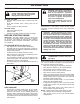
ASSEMBLY Your new tiller has been assembled at the factory with exception of those parts left unassembled for shipping purposes. To ensure safe and proper operation of your tiller all parts and hardware you assemble must be tightened securely. Use the correct tools as necessary to insure proper tightness. TOOLS REQUIRED FOR ASSEMBLY FRONT overhead_views_8 A socket wrench set will make assembly easier. Standard wrench sizes are listed.
ASSEMBLY INSTALL DEPTH STAKE ASSEMBLY UNPACK CARTON & INSTALL HANDLE (See Fig. 3) (See Fig. 2) • • CAUTION: Be careful of exposed staples when handling or disposing of cartoning material. • IMPORTANT: WHEN UNPACKING AND AS SEMBLING TILLER, BE CAREFUL NOT TO STRETCH OR KINK CABLE(S).
OPERATION KNOW YOUR TILLER READ THIS OWNER'S MANUAL AND SAFETY RULES BEFORE OPERATING YOUR TILLER. Compare the illustrations with your tiller to familiarize yourself with the location of various controls and adjustments. Save this manual for future reference. These symbols may appear on your Tiller or in literature supplied with the product. Learn and understand their meaning.
OPERATION The operation of any tiller can result in foreign objects thrown into the eyes, which can result in severe eye damage. Always wear safety glasses or eye shields before starting your tiller and while tilling. We recommend a wide vision safety mask for over spectacles or standard safety glasses. HOW TO USE YOUR TILLER TILLING Know how to operate all controls before adding fuel and oil or attempting to start engine.
OPERATION TO TRANSPORT CAUTION: Fill to within 1/2 inch of top of fuel tank to prevent spills and to allow for fuel expansion. If gasoline is accidentally spilled, move machine away from area of spill. Avoid creating any source of ignition until gasoline vapors have disappeared. Wipe off any spilled oil or fuel. Do not store, spill or use gasoline near an open flame. CAUTION: Before lifting or transporting, allow tiller engine and muffler to cool. Disconnect spark plug wire. Drain gasoline from fuel tank.
OPERATION NOTE: If at a high altitude (3000 feet) or in cold temperatures (below 32°F), the carburetor fuel mixture may need to be adjusted for best engine performance. See "TO ADJUST CARBURETOR" in the Service and Adjustments section of this manual. NOTE: If engine does not start, see troubleshooting points. • SPARK PLUG • THROTTLE CONTROL CHOKE CONTROL • RECOIL STARTER HANDLE eng ine _art _71 Soil conditions are important for proper tilling.
FILL IN DATES AS YOU COMPLETE REGULAR SERVICE BE FO R MAINTENANCE SCHEDULE EE EV AC ER HU Y5 SE HO EV ER UR Y2 S 5H EV O ER UR Y5 S 0H OU RS MAINTENANCE SERVICE DATES Check Engine Oil Level Change Engine Oil Oil Pivot Points Inspect Spark Arrester / Muffler Inspect Air Screen Clean or Replace Air Cleaner Cartridge 2 Clean Engine Cylinder Fins Replace Spark Plug 1 - Change more often when operating under a heavy load or in high ambient temperatures.
MAINTENANCE Disconnect spark plug wire before performing any maintenance (except carburetor adjustment) to prevent accidental starting of engine. Prevent fires! Keep the engine free of grass, leaves, spilled oil, or fuel. Remove fuel from tank before tipping unit for maintenance. Clean muffler area of all grass, dirt, and debris. Do not touch hot muffler or cylinder fins as contact may cause burns.
MAINTENANCE COOLING SYSTEM (See Fig. 14) MUFFLER Your engine is air cooled. For proper engine performance and long life keep your engine clean. • Clean air screen frequently using a stiff-bristledbrush. • Remove blower housing and clean as necessary. • Keep cylinder fins free of dirt and chaff. Do not operate tiller without muffler. Do not tamper with exhaust system. Damaged mufflers or spark arresters could create a fire hazard. Inspect periodically and replace if necessary.
SERVICE AND ADJUSTMENTS CAUTION: Disconnect spark plug wire from spark plug and place wire where it cannot come into contact with plug. TILLER MID-WIDTH TILLING - 22" PATH (See Fig. 17) • Assemble holes “A” in tine hubs to holes “C” in tine shaft. TO ADJUST HANDLE HEIGHT (See Fig. 15) Factory assembly has provided lowest handle height. Select handle height best suited for your tilling conditions. Handle height will be different when tiller digs into soil.
SERVICE AND ADJUSTMENTS TINE OPERATION CHECK (See Fig. 19) TO REMOVE BELT GUARD (See Fig. 20) • WARNING: Disconnect spark plug wire from spark plug to prevent starting while checking tine operation. • • • For proper tine operation, forward tine control lever must be against control body and all slack removed from inner wire of control cable when control is in the “OFF” (up) position. If lever and cable are loose, loosen cable clip at lower end of cable.
SERVICE AND ADJUSTMENTS ENGINE FORWARD MOTION (INSIDE) V-BELT ENGINE PULLEY BELT GUIDE TO ADJUST CARBURETOR TRANSMISSION PULLEY The carburetor has been preset at the factory and adjustment should not be necessary. However, engine performance can be affected by differences in fuel, temperature, altitude or load.
STORAGE Immediately prepare your tiller for storage at the end of the season or if the unit will not be used for 30 days or more. ENGINE OIL Drain oil (with engine warm) and replace with clean oil. (See “ENGINE” in the Maintenance section of this manual). WARNING: Never store the tiller with gasoline in the tank inside a building where fumes may reach an open flame or spark. Allow the engine to cool before storing in any enclosure.
TROUBLESHOOTING POINTS PROBLEM Will not start Hard to start Loss of power CAUSE CORRECTION 1. 2. 3. 4. 5. Out of fuel. Engine not “CHOKED” properly. Engine flooded. Dirty air cleaner. Water in fuel. 1. 2. 3. 4. 5. 6. 7. Clogged fuel tank. Loose spark plug wire. 6. 7. 8. 9. Bad spark plug or improper gap. Carburetor out of adjustment. 8. 9. 1. 2. 3. 4. 5. Throttle control not set properly. Dirty air cleaner. Bad spark plug or improper gap. Stale or dirty fuel. Loose spark plug wire. 1. 2. 3.
FRONT TINE TILLER – MODEL NUMBER MFT55 (MFG. ID. NO. 96081000602) HANDLE ASSEMBLY FT-handle_assy_1 KEY NO. 1 2 3 4 5 6 7 8 9 10 11 12 PART NO. 187820X421 72140512 165787 166376 73680500 19111116 19121414 74760520 74760516 10040500 73220500 98000129 DESCRIPTION Bracket, Handle Bolt, Carriage 5/16-18 x 1-1/2 Grip, Handle Handle, L.H.
FRONT TINE TILLER – MODEL NUMBER MFT55 (MFG. ID. NO. 96081000602) BELT GUARD AND PULLEY ASSEMBLY 41 1 2 3 4 17 5 30 42 6 8 7 10 29 11 31 29 11 11 12 12 9 13 11 27 28 14 15 19 26 20 25 24 16 23 22 32 21 18 KEY PART NO. NO.
FRONT TINE TILLER – MODEL NUMBER MFT55 (MFG. ID. NO. 96081000602) WHEEL AND DEPTH STAKE ASSEMBLY WHEEL?D STAKE? ?R KEY NO. 1 2 3 4 5 6 7 8 9 10 11 13 15 PART NO. 9194R 74760520 74760512 73220500 10040500 73800600 4921H 1952J 122233X 326J 74780628 1951J 5388J KEY NO.
FRONT TINE TILLER – MODEL NUMBER MFT55 (MFG. ID. NO. 96081000602) TINE ASSEMBLY 1 2 3 2 6 4 6 KEY NO. 1 2 3 4 5 6 PART NO. 156926 3146R 156924 156923 156925 4929H DESCRIPTION Tine, Outer, R.H. Retainer, Spring Tine, Inner, R.H. Tine, Inner, L.H. Tine, Outer, L.H.
FRONT TINE TILLER – MODEL NUMBER MFT55 (MFG. ID. NO. 96081000602) TRANSMISSION 20 1 2 3 5 6 11 19 18 17 16 8 14 11 10 7 10 14 10 12 KEY NO. 1 2 3 5 6 7 8 10 11 12 14 PART NO. 74760524 74780652 19131311 73900600 9057R421 188195 165834 73970500 187912 151222 9173R DESCRIPTION Bolt, Hex Head, Gr. 25/16-18 x 1-1/2 Bolt, Hex Head 3/8-16 x 3-1/4 Washer 13/32 x 13/16 x 11 Nut, Hex, Flangelock 3/8-16 Shield, Tine Bracket, Engine, R.H. Bracket, Engine, L.H.
FRONT TINE TILLER – MODEL NUMBER MFT55 (MFG. ID. NO. 96081000602) DECALS 5 4 1 6 7 2 8 11 10 13 KEY NO. 1 2 4 5 6 7 8 10 11 13 -- PART NO.
www.mcculloch.