
Specifications


3
3-4
McDATA Products in a SAN Environment - Planning Manual
Planning Considerations for Fibre Channel Topologies
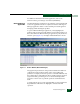
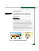
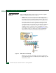
Part (A) of Figure 3-1 shows device D
1
connected to server S
1
through
a pair of H_Ports. Although the remaining switch H_Ports (six ports)
and device D
2
are unavailable for connection, frame traffic between
device D
1
and server S
1
travels through a loop that consists of all
eight H_Ports, device D
1
, device D
2
, and server S
1.
Each H_Port not
participating in the communication pair and the NL_Port on device
D
2
provide a repeater function that allows frames to pass around the
loop at the full switch bandwidth.
Part (B) of Figure 3-1 shows the logical equivalent of this arbitrated
loop. When frame transmission between device D
1
and server S
1
completes, the loop circuit closes and other ports attached to
initiating devices arbitrate for loop access. When operating in shared
mode, the switch is a serially reusable resource that provides service
access to all ports on the loop. Access is granted by successful
arbitration. When arbitration is won by a device, the loop is busy and
other arbitrating devices must wait for loop access.
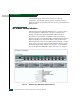
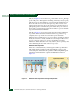
Switched Mode Operation
When set to switched mode, a switch bypasses full loop arbitration
and enables frame transmission through multiple point-to-point
connected pairs. Switched mode operation and its simplified logical
equivalent are illustrated for a Sphereon 4500 Fabric Switch in
Figure 3-2.
Figure 3-2 Switched Mode Operation and Logical Equivalent